
Self controlled intramedullary bone lengthening device

A technology of bone lengthening and suiting, applied in the field of medical devices, can solve the problems of long treatment period, low operation precision, troublesome operation, etc., and achieve the effect of shortening treatment time, prolonging high precision and facilitating nursing.

Inactive Publication Date: 2009-11-11
CHONGQING UNIV
View PDF6 Cites 0 Cited by
  • Summary
  • Abstract
  • Description
  • Claims
  • Application Information

AI Technical Summary

Problems solved by technology

[0004] The disadvantages are: limited extension range, long treatment period, many steel needle scars, difficult operation, all manual operation, low operation accuracy, and inherent complications of bone lengthening.
[0006] Its disadvantage is that the fixation stability of the extender is very poor, and it is generally not suitable for adult operations, and it is mostly used for children.
Although this device has the advantages of not damaging nerves and blood vessels, avoiding wound infection and swelling of limbs, and reducing skin scars, its disadvantages are: troublesome operation, patients cannot implement extension by themselves, and medical personnel need to use traction instruments to help each extension, and The traction force is difficult to control accurately, so the practicality is extremely poor
[0008] The common disadvantages of existing bone extenders are that they all use manual external force control to realize the stretching of the extender, the control precision of stretching is low, the operation is difficult, and the risk of misoperation in clinical application is extremely high
Moreover, it is easy to interfere and destroy blood circulation, which is not conducive to bone healing in the extended area.

Method used


Image

  • Self controlled intramedullary bone lengthening device
  • Self controlled intramedullary bone lengthening device
  • Self controlled intramedullary bone lengthening device

Examples


Embodiment Construction

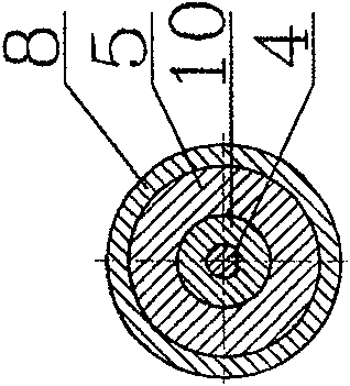
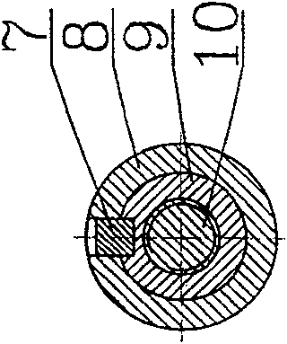
[0030] Please see figure 1 , figure 2 , image 3 , the present invention mainly consists of a left end fixed head 1, a steel washer 2, a left connecting sleeve 3, a motor 4, a motor bracket 5, a copper sleeve 6, a guide key 7, an outer sleeve 8, an inner sleeve 9, a central screw 10, and a steel washer 11. The right fixed head 12 is composed of one end of the left fixed head 1 and the left connecting sleeve 3, and the other end of the left connecting sleeve 3 is tightly connected with the motor bracket 5. The fastened connection can be threaded or interference Cooperate. The motor 4 part is installed in the motor bracket 5, the output shaft of the motor 4 is connected with the central screw rod 10, and the inner sleeve 9 engaged with it is set on the outer sleeve of the central screw rod 10, and the inner sleeve 9 is connected with the motor bracket 5 There is also a copper sleeve 6 between the sliding sleeves. On the one hand, the center screw 10 is positioned, and on th...


PUM


Abstract

The present invention is a self-controlled intramedullary bone extension device, which mainly consists of a left end fixed head (1), a left connecting sleeve (3), a motor (4), a motor bracket (5), a copper sleeve (6), and a guide key ( 7), outer sleeve (8), inner sleeve (9), center screw rod (10), right end fixed head (12) form. During the operation, it is inserted into the human bone marrow and connected to the bone with pins. When the motor rotates, the central screw rotates, and drives the inner sleeve to move axially in the inner sleeve around the threads, thereby stretching and extending the bone. When the motor does not rotate, the bone extension device is in a static state, and it plays an internal fixation role on the bone. Retraction can be achieved if the motor is reversed. The technical effects of the present invention are: small trauma, placed in the marrow cavity of the long bone, convenient for nursing and exercise, and beautiful. It can be used not only as an internal fixator, but also without external traction, and the patient can automatically control the bone extension according to the needs. The length can be adjusted arbitrarily, and the length of a single extension can be as small as 0.1mm, and the extension accuracy is high. It does not interfere and destroy blood circulation, which is beneficial to fracture healing or limb lengthening.

Description

technical field [0001] The invention relates to a medical device, in particular to a self-controlled intramedullary bone extension device. Background technique [0002] The lengthening technique used in the treatment of limb disparity originated from Codivilla's conception of bone lengthening, and has been improved and perfected by many scholars, gradually forming today's situation. And gradually extended to bone defect treatment, deformity correction and body heightening surgery. Traditional bone lengthening is mainly realized by external fixator, which is regarded as the key technology and equipment in bone lengthening, so external bone fixators with various spatial configurations and functions are derived. However, no matter how the external fixator is improved, the basic principle that it is placed on the surface of the limb and directly stretched outside the body has not changed. Therefore, the needle tract infection caused by the external fixator, a large number of sk...

Claims


Application Information

Patent Timeline
Patent Type & Authority Patents(China)
IPC IPC(8): A61F3/00A61B17/56A61F5/04
Inventor 唐朝伟何栎杨永齐胡军傅明怡
Owner CHONGQING UNIV
Learn More