Projection system and moire fringe eliminating method thereof

A projection system and moiré technology, applied in optics, instruments, projection devices, etc., can solve the problems of sacrificing the picture effect, difficult construction, unrealizable, etc., to ensure the brightness and resolution remain unchanged, eliminate the moiré phenomenon, and ensure show effect

Pending Publication Date: 2019-06-04
江苏镭创高科光电科技有限公司
View PDF10 Cites 2 Cited by
  • Summary
  • Abstract
  • Description
  • Claims
  • Application Information

AI Technical Summary

Problems solved by technology

[0003] At present, there are three main methods to eliminate moiré: 1. Change the position of the projector. However, this method is usually limited by the site environment and cannot be realized.
2. Cut the projection screen, use fewer pixels to project into the original required screen size, and change the positional relationship between the pixels and the sound hole by expanding the pixel spacing, thereby weakening the moiré. However, this method It will reduce the brightness and resolution of the projected picture, which is equivalent to sacrificing the picture effect
3. Replace with a micro-hole curtain, that is, reduce the diameter of the sound-transmitting hole. However, this method is expensive and difficult to construct, which virtually increases the cost.

Method used


Image

  • Projection system and moire fringe eliminating method thereof
  • Projection system and moire fringe eliminating method thereof
  • Projection system and moire fringe eliminating method thereof

Examples


Embodiment Construction

[0034] The above is the core idea of ​​the present invention. In order to make the above-mentioned purposes, features and advantages of the present invention more obvious and easy to understand, the technical solutions in the embodiments of the present invention will be clearly and completely described below in conjunction with the accompanying drawings in the embodiments of the present invention Description, obviously, the described embodiments are only a part of the embodiments of the present invention, rather than all the embodiments. Based on the embodiments of the present invention, all other embodiments obtained by persons of ordinary skill in the art without making creative efforts belong to the protection scope of the present invention.

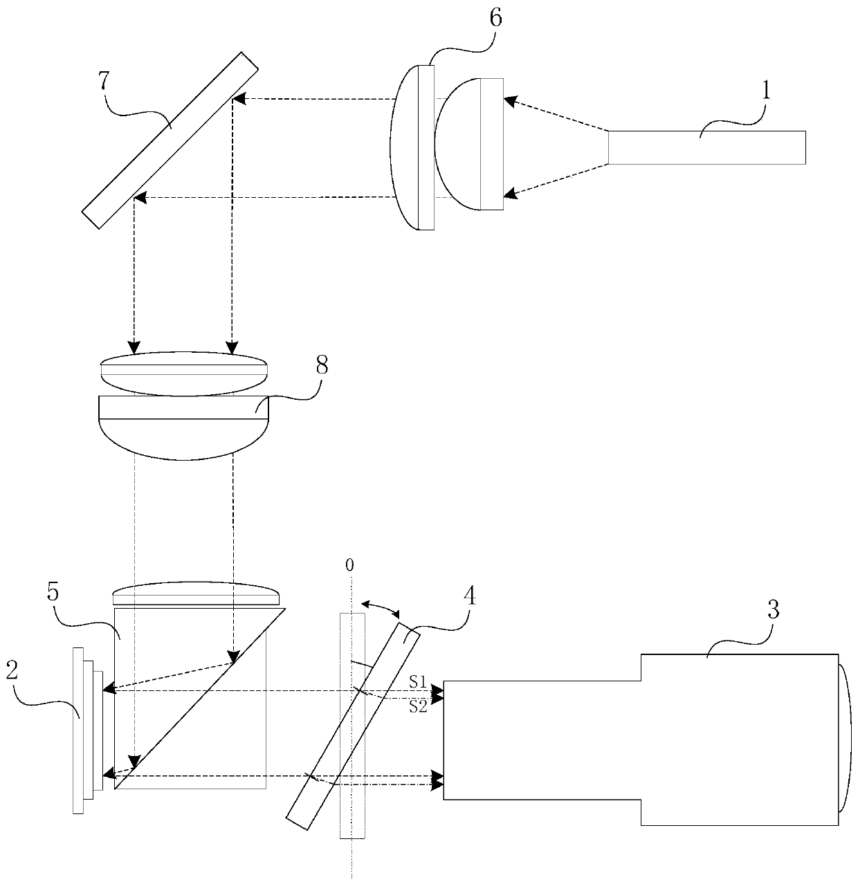
[0035] An embodiment of the present invention provides a projection system, such as figure 1 As shown, the projection system includes a light source 1 and a DMD array 2 sequentially located on the light path of the light source 1, a p...


PUM


Abstract

The invention provides a projection system and a moire fringe eliminating method thereof. The projection system includes a light source, and a DMD array and a projection lens located on the light pathof the light source in turn. The projection system further includes a device for eliminating moire fringes. The device for eliminating moire fringes includes a light transmission element and a driving assembly for driving the light transmission element, and the light transmission element is located between the DMD array and the projection lens. The driving assembly is used for driving the light transmission element to vibrate repeatedly between a first deflection state and a second deflection state, so that the light emitted by the DMD array moves back and forth between a first outgoing lightpath and a second outgoing light path after passing through the light transmission element, and the pixels projected by the projection lens onto the screen move back and forth between a first position and a second position. Therefore, the fixed position relationship between the pixels and the sound transmission holes can be destroyed through the changing positions of the pixels, and the moire fringes on the screen can be reduced or eliminated.

Description

technical field [0001] The invention relates to the technical field, more specifically, to a projection system and a method for eliminating moiré. Background technique [0002] In the field of projection, when the pitch of sound holes on the screen is in a certain positional relationship with the vertical and horizontal pixel pitch of the projector DMD (Digital Micro-mirror Device) and the projection distance, a phenomenon similar to water will appear on the screen. The gray (or color) interference fringes of the pattern, that is, the moiré pattern. [0003] At present, there are three main methods to eliminate moiré: 1. Change the position of the projector. However, this method is usually limited by the site environment and cannot be realized. 2. Cut the projection screen, use fewer pixels to project into the original required screen size, and change the positional relationship between the pixels and the sound hole by expanding the pixel spacing, thereby weakening the moir...

Claims


Application Information

Patent Timeline
Patent Type & Authority Applications(China)
IPC IPC(8): G03B21/00G03B21/14G03B21/20
Inventor 高文宏刘灵芝郭泽彬李孟
Owner 江苏镭创高科光电科技有限公司
Why Eureka
Try Eureka