
Button structure

A key and keycap technology, applied in the field of key structures with multiple trigger functions, can solve problems such as signal speed drop

Inactive Publication Date: 2019-06-04
QUNGUANG OPTOELECTRONICS SUZHOU
View PDF7 Cites 0 Cited by
  • Summary
  • Abstract
  • Description
  • Claims
  • Application Information

AI Technical Summary

Problems solved by technology

If the same button needs to switch to different input signals, you must press multiple buttons at once or switch to different input modes first, but this input method will cause the speed of signal generation to drop

Method used


Image

  • Button structure
  • Button structure
  • Button structure

Examples


Embodiment Construction

[0037] In order to enable your review committee members to better understand the technical content of the present invention, the preferred specific embodiments are described as follows.

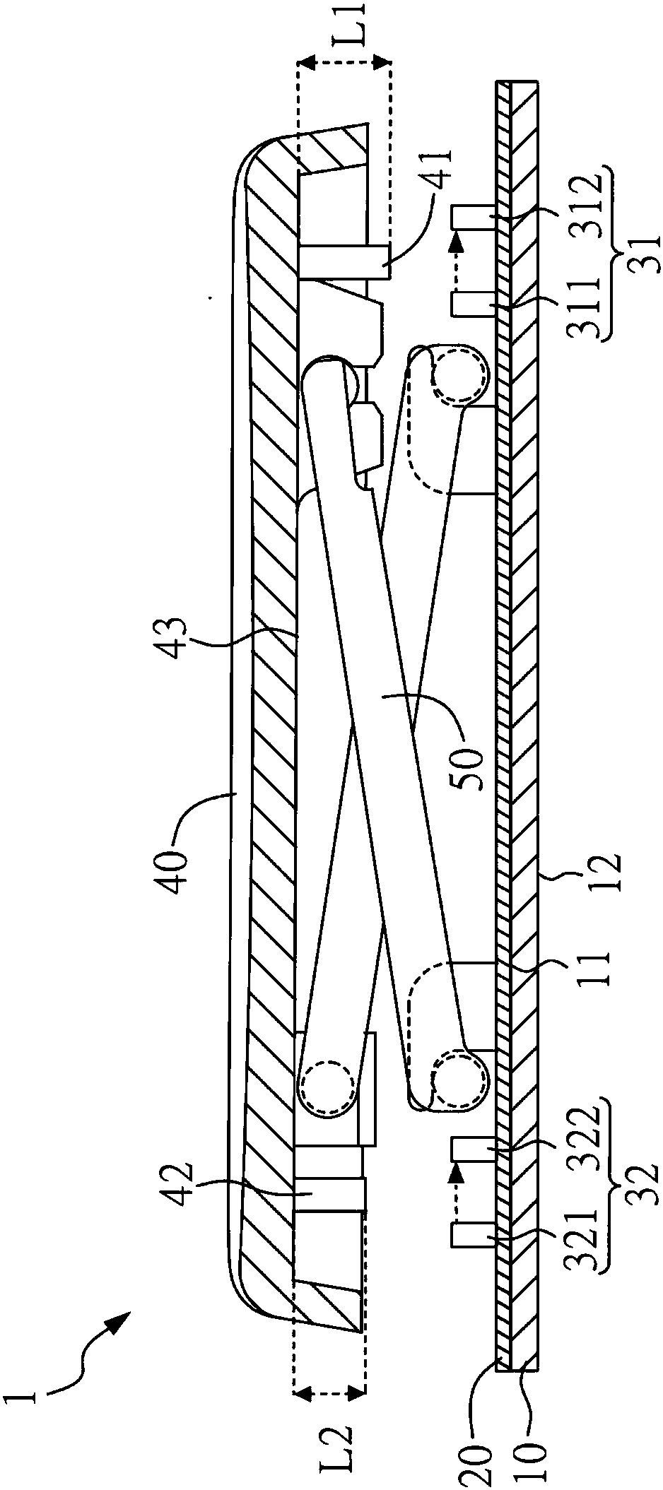
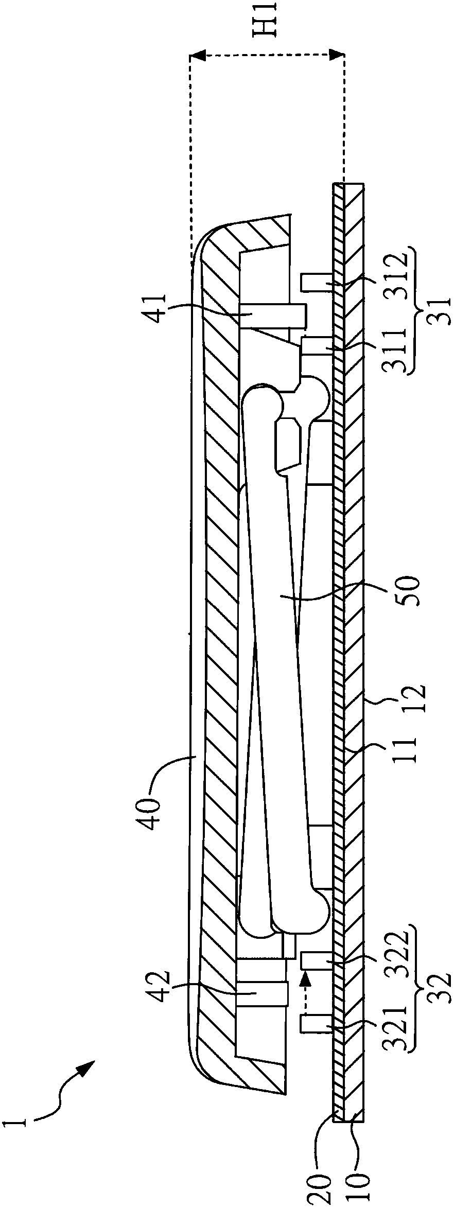
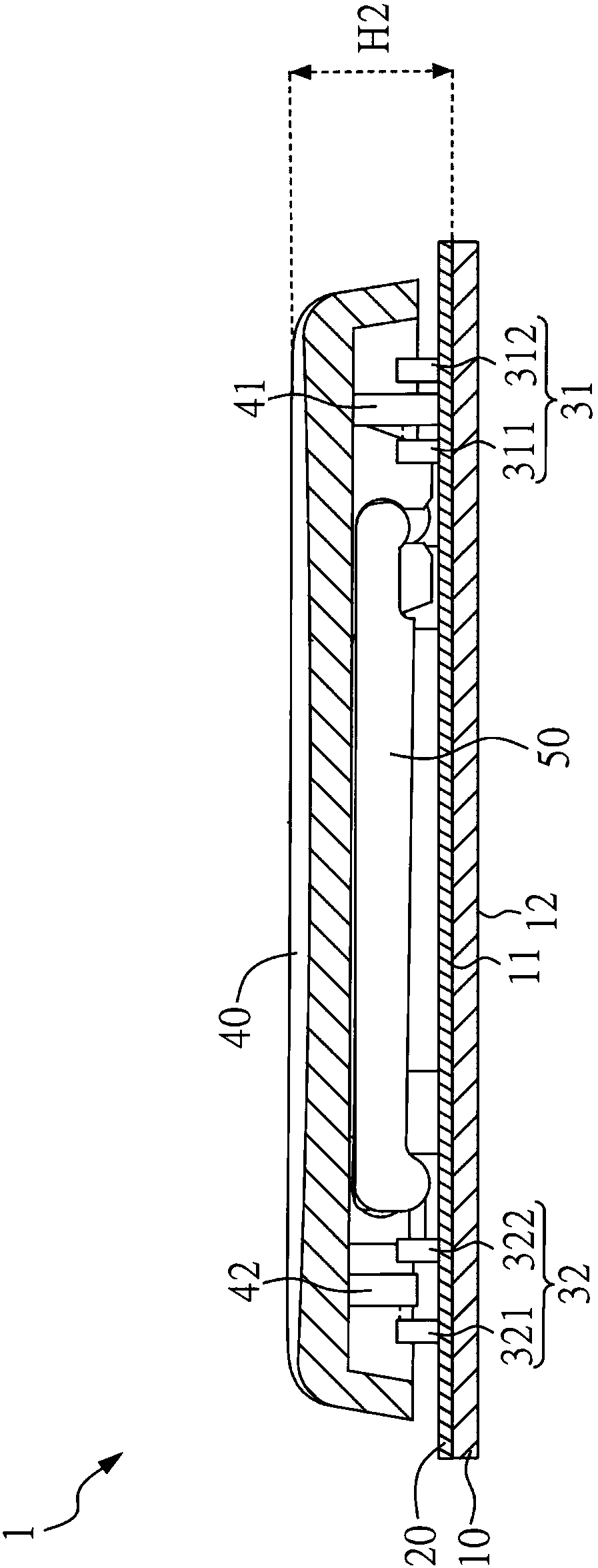
[0038] Figure 1A It is a schematic cross-sectional view of the button structure of the first embodiment of the present invention, please refer to Figure 1A shown. The button structure 1 of this embodiment includes a bottom plate 10 , a circuit board 20 , a first optocoupler assembly 31 , a second optocoupler assembly 32 , a keycap 40 and a scissors connector 50 . The circuit board 20 is disposed on one surface of the base plate 10 . In this embodiment, the upper surface 11 of the base plate 10 is taken as an example. In other embodiments, the circuit board 20 may also be disposed on the lower surface 12 of the base plate 10 , which will be further described later.

[0039] The key structure 1 of the present embodiment has two optocoupler components, which are respectively referred to as a f...


PUM


Abstract

The invention discloses a button structure which comprises a bottom plate, a circuit board, a first optocoupler assembly, a second optocoupler assembly, a keycap and a scissor type connector. The circuit board is arranged on one surface of the bottom plate. The first optocoupler assembly and the second optocoupler assembly are arranged on the circuit board. The key cap has a first light blocking member and a second light blocking member, the first light blocking member is corresponding to the first photocoupler assembly, the second light blocking member is corresponding to the second photocoupler member, and the length of first light blocking member is larger than the length of the second light blocking member. The scissor type connector is connected to the keycap and the bottom plate. Thefirst light blocking member triggers the first optocoupler assembly when the keycap is at a first trigger height relative to the bottom plate. The second light blocking member triggers the second optocoupler assembly when the keycap is at a second trigger height relative to the bottom plate.

Description

technical field [0001] The present invention relates to a key structure, in particular to a key structure with multiple trigger functions. Background technique [0002] In terms of current computer usage habits, the keyboard is one of the indispensable input devices. Generally speaking, the keyboard has a plurality of key structures, and each key structure has only a single trigger structure, each press generates a single trigger signal, and correspondingly generates a single input signal. [0003] In other words, when one of the buttons is pressed, the same input signal is correspondingly generated regardless of the pressing degree (full press or half press). If the same button needs to switch to different input signals, it is necessary to press multiple buttons at one time or switch to different input modes first, but this input method will cause the speed of signal generation to decrease. [0004] Therefore, how to provide a button structure with multiple trigger functi...

Claims


Application Information

Patent Timeline
Patent Type & Authority Applications(China)
IPC IPC(8): H01H13/02H01H13/66
Inventor 陈建硕辜宛贞
Owner QUNGUANG OPTOELECTRONICS SUZHOU
Learn More