
Gap forced triggering device and alternating-current controllable lightning arrester

A technology of triggering device and arrester, which is applied in the direction of overvoltage arrester, spark gap, spark gap components, etc., which can solve the problem of complex trigger energy supply system, and achieve the effect of forced trigger function of the gap

Active Publication Date: 2021-04-30
CHINA ELECTRIC POWER RES INST
View PDF5 Cites 0 Cited by
  • Summary
  • Abstract
  • Description
  • Claims
  • Application Information

AI Technical Summary

Problems solved by technology

[0005] In view of this, the present invention proposes a gap forced trigger device and an AC controllable lightning arrester, aiming at solving the problem of self-discharge gaps that cannot meet the technical requirements and forced trigger gaps Triggering complex issues in energy supply systems via external triggering energy sources

Method used


Image

  • Gap forced triggering device and alternating-current controllable lightning arrester
  • Gap forced triggering device and alternating-current controllable lightning arrester
  • Gap forced triggering device and alternating-current controllable lightning arrester

Examples


Embodiment Construction

[0025] Exemplary embodiments of the present disclosure will be described in more detail below with reference to the accompanying drawings. Although exemplary embodiments of the present disclosure are shown in the drawings, it should be understood that the present disclosure may be embodied in various forms and should not be limited by the embodiments set forth herein. Rather, these embodiments are provided for more thorough understanding of the present disclosure and to fully convey the scope of the present disclosure to those skilled in the art. It should be noted that, in the case of no conflict, the embodiments of the present invention and the features in the embodiments can be combined with each other. The present invention will be described in detail below with reference to the accompanying drawings and examples.

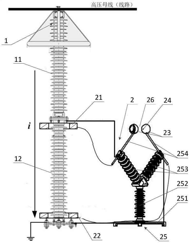
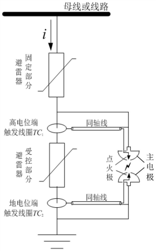
[0026] see Figure 2 to Figure 3 , which shows a preferred structure of the AC controllable arrester provided by the embodiment of the present invention. As...


PUM


Abstract

The invention provides a gap forced triggering device and an alternating-current controllable lightning arrester. The device comprises a high potential end trigger coil, a ground potential end trigger coil, two main electrodes and two ignition electrodes, wherein a main gap is formed between the two main electrodes, the two ignition electrodes are in one-to-one correspondence with the two main electrodes, and an ignition gap is formed between each ignition electrode and the corresponding main electrode; the two ends of the high potential end trigger coil are electrically connected with one main electrode and one ignition electrode respectively, and the two ends of the ground potential end trigger coil are electrically connected with the other main electrode and the other ignition electrode respectively. The controllable lightning arrester is used as a trigger energy source, a voltage trigger pulse is generated when action current flows through a controlled part through the high potential end trigger coil and the ground potential end trigger coil, output voltage is led out to the ignition gap, the ignition gap is broken down under the action of the voltage trigger pulse to discharge to generate initial plasma, and the main gap is broken through and conducted, so that the controlled part is short-circuited.

Description

technical field [0001] The invention relates to the technical field of power system overvoltage protection, in particular to a gap forced trigger device and an AC controllable lightning arrester. Background technique [0002] In EHV and UHV power systems, if the overvoltage level can be deeply reduced, it will be very beneficial to the design of system insulation coordination and the difficulty of manufacturing power transmission and transformation equipment. Controllable surge arrester technology is a flexible limitation technology for system overvoltage that adapts to changes in operating conditions. [0003] see figure 1 , the controllable arrester is composed of a fixed part and a controlled part, and a controllable unit is connected in parallel at the controlled part of the arrester. When the system is running normally, the controllable unit is disconnected, and the arresters of the fixed part and the controlled part are put into operation; when the system is overvolt...

Claims


Application Information

Patent Timeline
Patent Type & Authority Applications(China)
IPC IPC(8): H01T4/10H01T4/02H01T1/16
CPCH01T4/10H01T4/02H01T1/16
Inventor 李国富余辉董勤晓李志远李会兵刘赫
Owner CHINA ELECTRIC POWER RES INST
Learn More