Movable dumbbell frame adjustable in height

A height-adjustable and adjustable technology, applied in the direction of dumbbells, heavy objects, etc., can solve the problems of adjustment, increase safety hazards, and non-adjustable height of light dumbbell racks, so as to achieve the effect of convenient use and reduce safety hazards

Inactive Publication Date: 2019-06-07
TIANJIN AOLIN
0 Cites 1 Cited by

AI-Extracted Technical Summary

Problems solved by technology

[0002] At present, dumbbell racks are mostly fixed due to their large load-bearing capacity. A small number of light dumbbell racks for families use movable pulleys. However, the height of these light dumbbell racks cannot be adjusted, and trainers of different heights cannot adjust according to the actual situation when using them. It makes it inconvenient to pick and place the dumbbells; when the universal wheels of the existing dumbbell rack ar...

Abstract

The invention discloses a movable dumbbell frame adjustable in height. The movable dumbbell frame comprises a base, wherein a pair of parallel directional pulleys and a pair of self-locking universalwheels are arranged at the bottom of the base; a lower supporting beam is fixedly arranged on one side of the top of the base, a height adjusting pipe is slidably arranged in a sliding groove in the lower supporting beam, and a plurality of through holes are formed in the side wall of the height adjusting pipe; a positioning hole is formed in the side wall of the lower supporting beam, and a positioning knob is inserted into the positioning hole; the positioning knob is in threaded connection with the positioning hole and penetrates through one through hole in the height adjusting pipe after being screwed into the positioning hole; an upper cross beam is fixedly arranged at the top of the height adjusting pipe, and dumbbell supports fixedly sleeve the two ends of the upper cross beam. Thedumbbell supports can be adjusted at multiple heights, so that trainees of different heights can conveniently use the dumbbell frame; when the self-locking universal wheels are locked, wheel shafts ofthe universal wheels and a steering shaft can be locked at the same time, so that locking is more stable, and the dumbbell falling risk is reduced; in the moving process, a brake handle can be used for braking in time, so that potential safety hazards are reduced.

Application Domain

Dumb-bells

Technology Topic

EngineeringSelf locking +4

Image

  • Movable dumbbell frame adjustable in height
  • Movable dumbbell frame adjustable in height
  • Movable dumbbell frame adjustable in height

Examples

  • Experimental program(1)

Example Embodiment

[0018] The present invention will be further described below in conjunction with the drawings and embodiments:
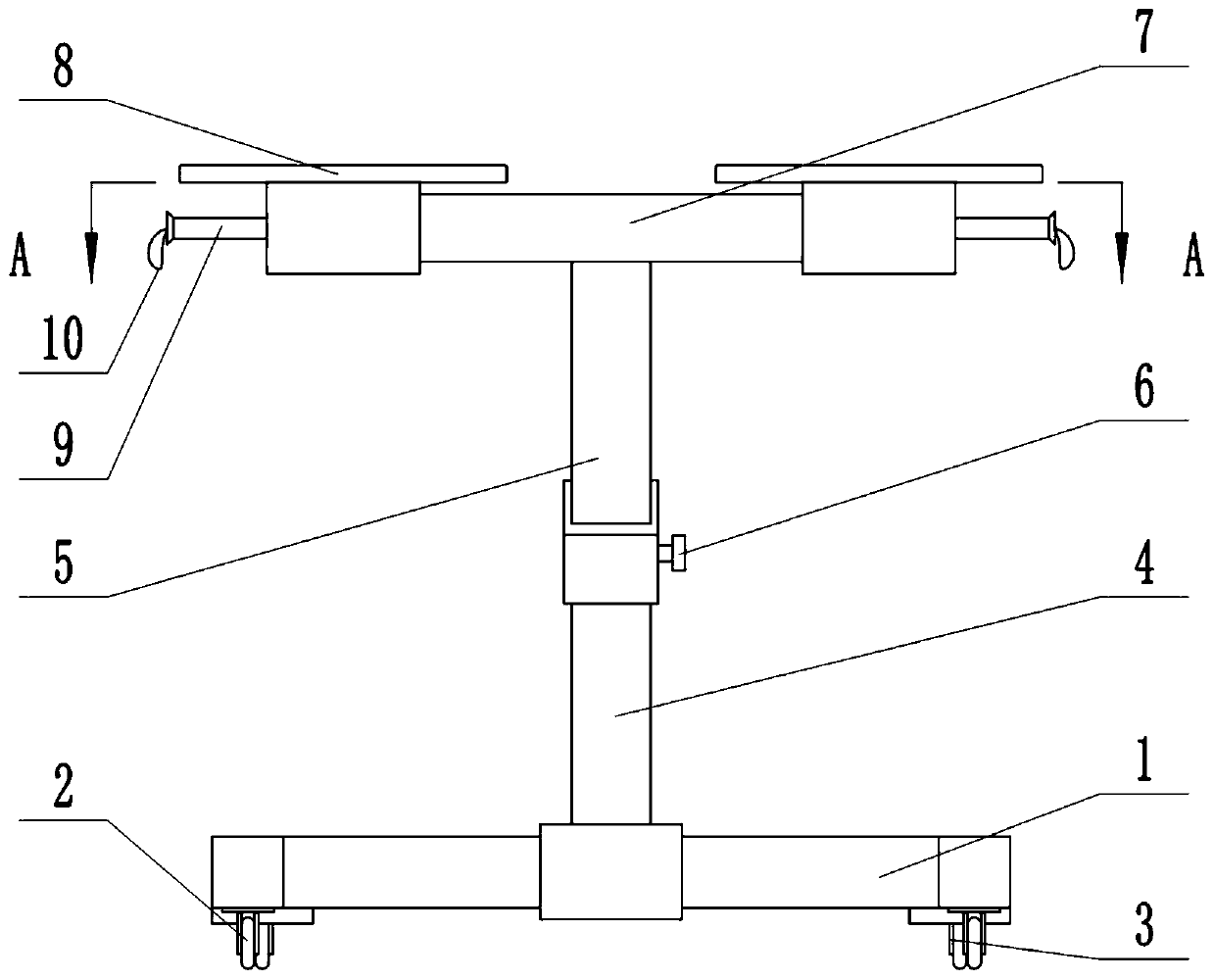
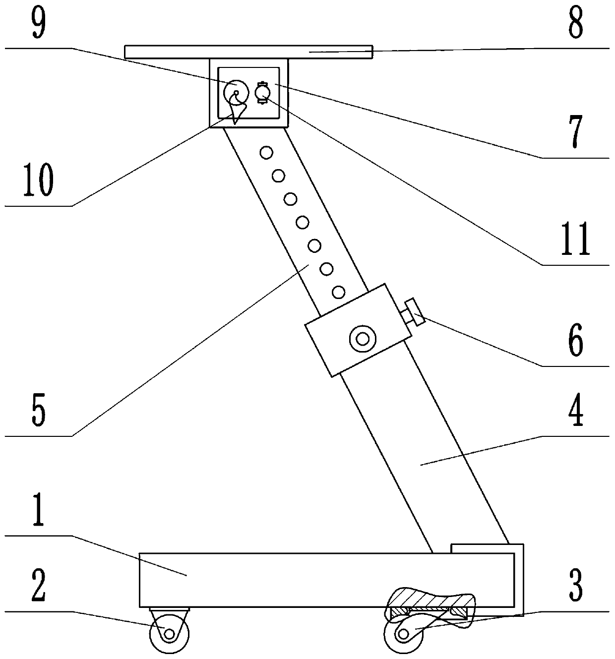
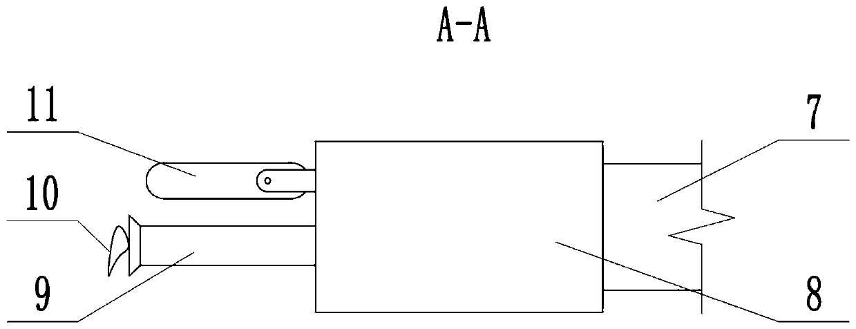
[0019] As shown in the figure, a height-adjustable mobile dumbbell rack includes a base 1, a pair of parallel directional pulleys 2 and a pair of self-locking universal wheels 3 are arranged at the bottom of the base 1, and the top side of the base 1 is fixed Lower support beam 4, lower support beam 4 is provided with a chute with an upward opening and a height adjustment tube 5 is slid in the slide groove. A number of through holes are provided on the side wall of height adjustment tube 5, and the side wall of lower support beam 4 A positioning hole is provided on the positioning hole, and a positioning knob 6 is inserted into the positioning hole. The positioning knob 6 is screwed into the positioning hole and passes through a through hole on the height adjustment tube 5. The top of the height adjustment tube 5 is fixedly provided with an upper Both ends of the cross beam 7 and the upper cross beam 7 are fixedly sleeved with dumbbell rests 8.
[0020] Preferably, both ends of the upper beam 7 are fixedly provided with handles 9, and an end of the handle 9 away from the upper beam 7 is provided with a rope sleeve 10.
[0021] Preferably, both ends of the upper beam 7 are hinged with brake handles 11, the self-locking universal wheel 3 includes a universal wheel 31, and a plurality of sliding tubes 32 are provided on the side wall of the fixed seat of the universal wheel 31, and the sliding tube 32 is externally provided There is a rubber block 33. The rubber block 33 is provided with a groove and the inner wall of the groove is slidably connected with the slide tube 32. A spring 34 is provided between the rubber block 33 and the fixed seat of the universal wheel 31. The spring 34 is sleeved outside the slide tube 32. A wire rope 35 is slidably provided in the sliding tube 32. One end of the wire rope 35 is fixedly connected with the inner end of the groove of the rubber block 33, and the other end is connected with a brake wire in the fixing seat of the universal wheel 31, and the sliding sleeve of the brake wire is provided with a brake wire The brake cable pipe is fixedly arranged along the inner wall of the universal wheel 31 fixing seat, the base 1, the lower support beam 4, the height adjustment tube 5 and the upper cross beam 7 in sequence, and the other end of the brake cable is fixedly connected with the inner end of the brake handle 11.
[0022] Preferably, the base 1 is a U-shaped square tube.
[0023] Preferably, the height adjustment tube 5 is a square tube and both side walls are provided with through holes, and both side walls of the lower support beam 4 are provided with positioning holes correspondingly.
[0024] Preferably, the lower support beam 4 is arranged obliquely.
[0025] When the present invention is used, by adjusting the relative position of the height adjusting tube 5 and the lower support beam 4 and locking with the positioning knob 6, multiple height adjustments of the dumbbell holder 8 can be realized, which facilitates the use of trainers of different heights; self-locking universal wheel 3 When locked, the rubber block 33 is stuffed between the wheel body of the universal wheel 31 and the lower wall of the base 1, which can lock the wheel shaft and the steering shaft of the universal wheel 31 at the same time, making the locking more stable and reducing the risk of dumbbell falling; During the movement of the present invention, the brake handle 11 can be pulled to brake. The brake handle 11 pulls the wire rope 35 through the brake wire in the brake wire tube, so that the rubber block 33 is close to the fixed seat of the universal wheel 31 and is inserted into the wheel body of the universal wheel 31 and The timely braking between the lower wall of the base 1 avoids accidents caused by insufficient arm strength and effectively reduces potential safety hazards; in addition, the brake lever 11 is located next to the handle 9, so that the trainer only needs to put the rope sleeve 10 on the brake lever 11 Lock up without bending over.
[0026] The present invention is exemplarily described above in conjunction with the accompanying drawings. Obviously, the specific implementation of the present invention is not limited by the above-mentioned manners, as long as various improvements made by the method concept and technical solutions of the present invention are adopted, or directly applied to others without improvement. All occasions fall within the protection scope of the present invention.

PUM

no PUM

Description & Claims & Application Information

We can also present the details of the Description, Claims and Application information to help users get a comprehensive understanding of the technical details of the patent, such as background art, summary of invention, brief description of drawings, description of embodiments, and other original content. On the other hand, users can also determine the specific scope of protection of the technology through the list of claims; as well as understand the changes in the life cycle of the technology with the presentation of the patent timeline. Login to view more.

Similar technology patents

Disposable medical-examination light

ActiveUS20090097236A1good visualizationeasy to use
Owner:UTAH MEDICAL PRODS

Patient positioning support structure

ActiveUS20120198625A1easy to useinexpensive to make
Owner:WARSAW ORTHOPEDIC INC

Classification and recommendation of technical efficacy words

  • Reduce security risks
  • easy to use

Automatic driving system

Owner:CHERY AUTOMOBILE CO LTD

Power safety socket device

ActiveCN106848698AReduce security risksImprove power supply stability
Owner:东莞科奔电器有限公司

Method for optimizing and balancing power-cut schemes

InactiveCN104156790AReduce security risksReduce the number of outages
Owner:STATE GRID CORP OF CHINA +2

Laser assisted total joint arthroplasty

InactiveUS20090234360A1easy to use
Owner:ALEXANDER VLADIMIR

Enclosure for a portable hemodialysis system

ActiveUS20090114582A1easy to use
Owner:DEKA PROD LLP
Why Eureka
Try Eureka