Improved structure of water-saving closestool

A toilet and stool technology, which is applied in the field of sanitary ware, can solve the problems of user inconvenience and lack of flushing water, and achieve the effect of using stool and convenient use

Pending Publication Date: 2019-06-07
佛山市己阿已磁电设备有限公司
View PDF0 Cites 0 Cited by
  • Summary
  • Abstract
  • Description
  • Claims
  • Application Information

AI Technical Summary

Problems solved by technology

[0002] In the existing water-saving toilets that use microbial treatment to achieve water-saving effects, the stool directly falls into the microbial treatment mechanism. In order to prevent flushing water from entering the microbial treatment mechanism, no flushing water can flow through the microbial treatment mechanism.
And pres

Method used


Image

  • Improved structure of water-saving closestool
  • Improved structure of water-saving closestool
  • Improved structure of water-saving closestool

Examples


Embodiment 1

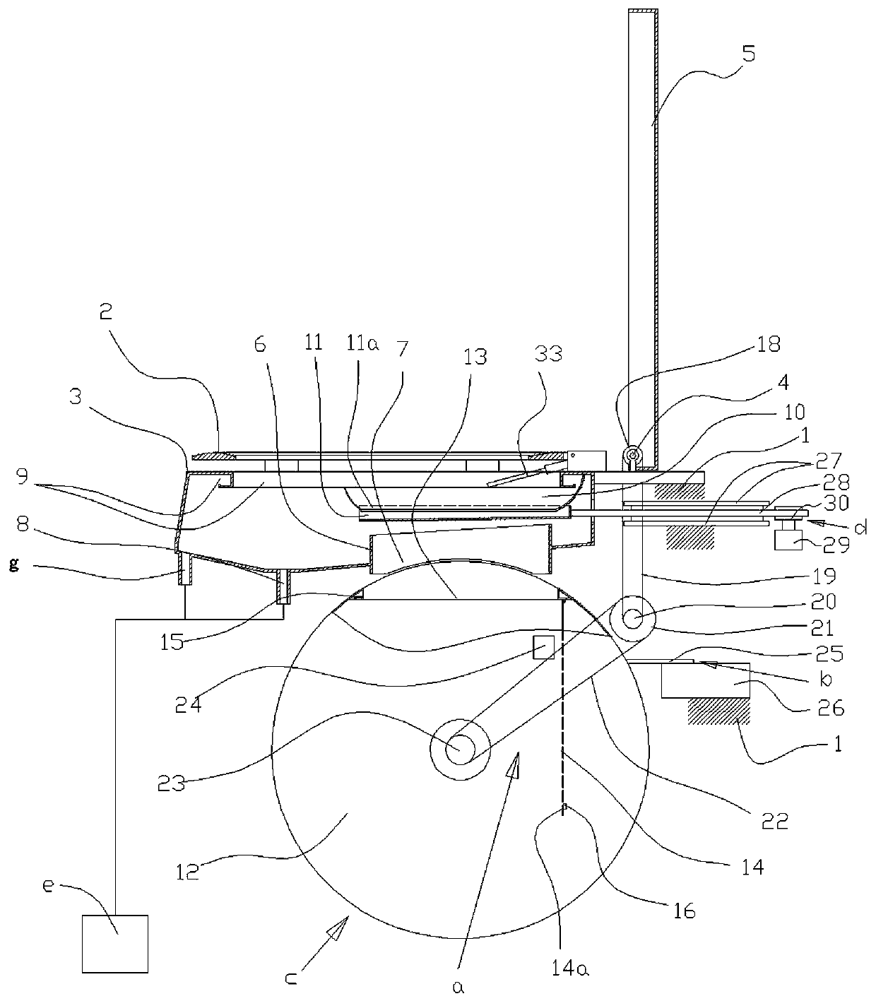
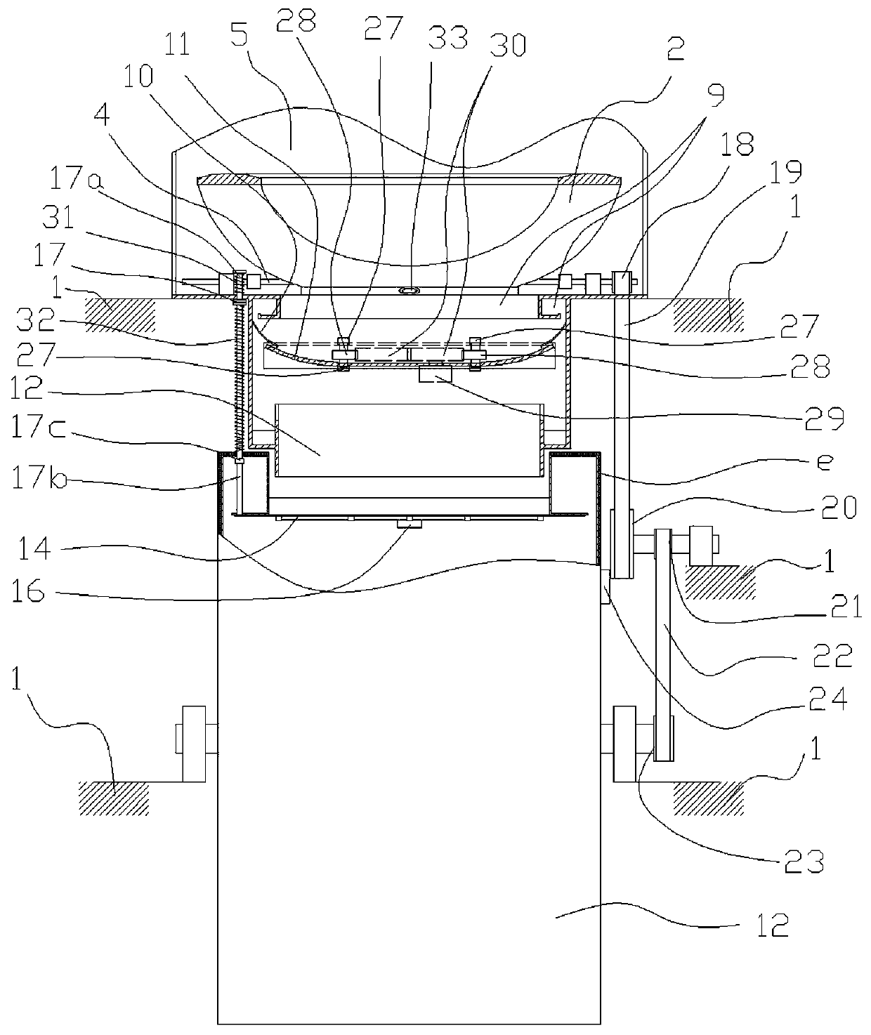
[0023] Embodiment 1: as figure 1 , 2 As shown, it includes a base 1, a toilet pocket 3 with a smart toilet lid-type seat plate 2 arranged on the base 1, a cover plate arranged on the toilet pocket 3 and connected to the base 1 by rotating a shaft 4 5. The stool discharge opening 7 with the flange 6 around the rear part of the toilet pocket 3, the microbial treatment mechanism c located below the stool discharge opening 7, and the urine collection container e arranged on the toilet pocket 3 outside the stool discharge opening 7 The connected urine discharge port 8 is special in that a shutter 11 driven by power d to move back and forth is set above the stool discharge port 7, and the power d is electric power, including a screen that is fixedly connected with the screen 11 and moves back and forth along the track 27. A pair of racks 28 that move, a motor 29 , a pair of gears 30 meshed with each other driven by the motor 29, and a pair of gears 30 mesh with a pair of racks 28 r...

Embodiment 2

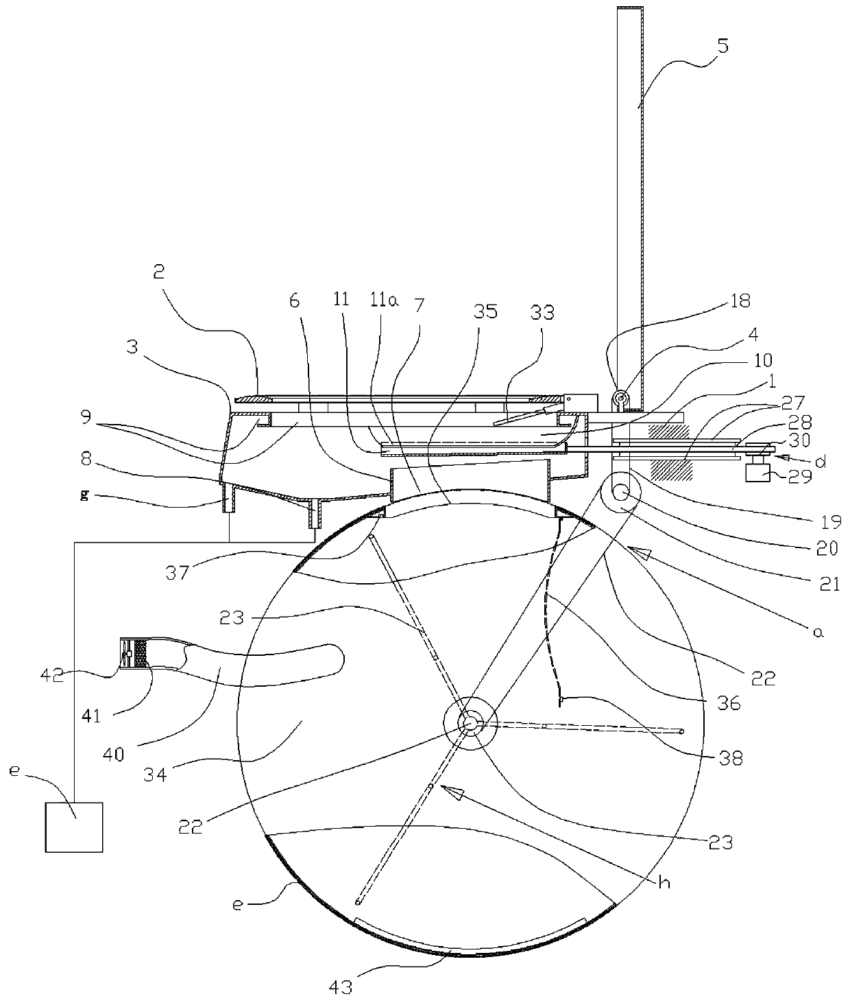
[0034] Embodiment 2: as image 3 As shown, this embodiment is on the basis of Embodiment 1. The microorganism treatment mechanism c includes a horizontally arranged cylinder 34 arranged under the toilet bag 3, and an agitator h is arranged to rotate on the middle horizontal line in the cylinder 34. The cylinder 34 The upper side wall is provided with an opening 35 facing the stool discharge port 7, and a cover door 36 is arranged in the tube below the opening 35. The rotation axis of the cover door 36 is parallel to the agitator axis of the tube 34, corresponding to the free edge of the cover door 35. A magnetic attraction 37 is provided on the inner side wall of the cylinder 34, and a magnetic conductor 38 is provided on the free side of the cover door 36 corresponding to the magnetic attraction 37, and a pressing rod 17 is provided on the cylinder side wall corresponding to the edge of the cover door 36 away from the shaft axis. (Same structure and function as in Embodiment ...


PUM


Abstract

The invention provides an improved structure of a water-saving closestool. The improved structure comprises a base, a closestool pocket, a cover plate, a feces discharge port, a microbial treatment mechanism and a urine discharge port, wherein the closestool pocket is arranged on the base and provided with a seat board containing an intelligent closestool cover, the cover plate is arranged on theclosestool pocket and rotationally connected to the base through a rotating shaft, the feces discharge port is formed in rear of the closestool pocket, the periphery of the feces discharge port is provided with a flange, the microbial treatment mechanism is located under the feces discharge port, the urine discharge port is formed in the closestool pocket at the outer side of the feces discharge port and communicated with a urine collecting container; the improved structure is characterized in that a shielding plate driven by power to move back and forth is arranged above the feces discharge port, wherein the power is electric power or power transmitted by the rotating shaft of the cover plate through a transmission mechanism. Compared with the prior art, the improved structure of the water-saving closestool has the advantages that the closestool cover can be flushed, the use is convenient, and feces does not need to be flushed.

Description

technical field [0001] The invention relates to a sanitary appliance, in particular to a toilet. Background technique [0002] In the existing water-saving toilets that achieve water-saving effect through microbial treatment, the feces directly fall into the microbial treatment mechanism. In order to prevent flushing water from entering the microbial treatment mechanism, no flushing water can flow through the microbial treatment mechanism. And present toilet, a lot of all have flushing toilet cover (smart toilet cover), and after people defecate, the stool excretion position is cleaned by flushing toilet cover, like this, the above-mentioned water-saving toilet of the prior art just can't use Such flushing just covers, and this just brings very big inconvenience to the user. Contents of the invention [0003] The object of the present invention is to provide an improved structure of an easy-to-use water-saving toilet that can use a flush toilet cover. [0004] The presen...

Claims


Application Information

Patent Timeline
IPC IPC(8): E03D11/10
Inventor 李泽
Owner 佛山市己阿已磁电设备有限公司
Why Eureka
Try Eureka