Deflection measuring device and method for mechanical arms of engineering vehicles

A technology for measuring devices and engineering vehicles, which is applied in the direction of measuring devices, optical devices, instruments, etc., can solve problems such as high technical requirements and complex installation structures of deflection measuring devices, and achieve simple operation steps, convenient installation, intuitive and accurate detection results. precise effect

Inactive Publication Date: 2019-06-07
CHINA RAILWAY CONSTR HEAVY IND
View PDF9 Cites 8 Cited by
  • Summary
  • Abstract
  • Description
  • Claims
  • Application Information

AI Technical Summary

Problems solved by technology

In another patent document, an in-situ monitoring system for measuring the deflection of parts, the detection system used is only suitable for small parts
Moreover, there is no device and supporting method for deflection measurement for the actual situation of the rock drilling rig
[0004] In view of the shortcomings of the prior art described above, a high-precision, simple and feasible deflection measuring device for engineering vehicle mechanical arms is needed to solve the problems of the prior art that the installation of the deflection measuring device and the structure are too complicated and the technical requirements are high

Method used


Image

  • Deflection measuring device and method for mechanical arms of engineering vehicles
  • Deflection measuring device and method for mechanical arms of engineering vehicles
  • Deflection measuring device and method for mechanical arms of engineering vehicles

Examples


Embodiment Construction

[0046] In order to make the object, technical solution and advantages of the present invention clearer, the embodiments of the present invention will be further described in detail below in conjunction with the accompanying drawings.

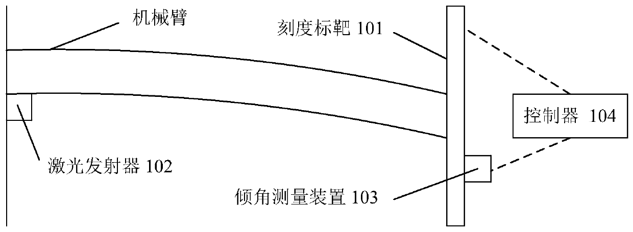
[0047] figure 1 A schematic structural diagram of a deflection measuring device for a mechanical arm of an engineering vehicle according to an embodiment of the present invention is shown. like figure 1 As shown, the deflection measuring device includes a scale target 101 , a laser emitter 102 , an inclination measuring device 103 and a controller 104 .

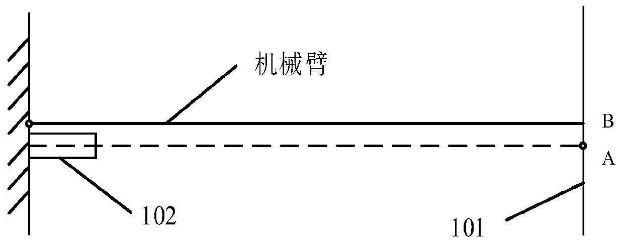
[0048] Wherein, the scale target 101 is installed at the end of the boom of the robot arm, and is perpendicular to the direction of the extension line of the robot arm when there is no deflection deformation of the robot arm. Further, the scale target 101 is provided with a readable scale for displaying the position information of the laser spot.

[0049]In this embodiment, the readable scal...


PUM


Abstract

The invention provides a deflection measuring device for mechanical arms of engineering vehicles, comprising a calibration target which is installed at the end of a movable arm of a mechanical arm andis perpendicular to the extension line direction of the mechanical arm under no deflection deformation of the mechanical arm, a laser emitter which is installed at the root of a fixed arm of the mechanical arm and is used for emitting laser to the calibration target along a direction parallel to the axis of the fixed arm to leave identifiable laser spots on the calibration target, an inclinationangle measuring device which is installed on the calibration target and is used for measuring the included angle produced by the calibration target before and after deflection deformation of the mechanical arm, and a controller which is used for acquiring the position information of the laser spots on the calibration target and the included angle measured by the inclination angle measuring deviceand calculating the deflection of the mechanical arm after deflection deformation. The deflection measuring device adopted by the invention is relatively convenient in installation, the use and operation steps are relatively simple, and the detection results are intuitive and accurate. The safety of engineering vehicles in mechanical operation is improved.

Description

technical field [0001] The invention relates to the field of engineering measurement, in particular to a deflection measuring device and method for a mechanical arm of an engineering vehicle. Background technique [0002] Many current engineering machinery have mechanical arms, such as cranes and rock drilling rigs. When such engineering vehicles with mechanical arms are hoisting, the originally straight arm will be bent and deformed due to the lifting weight. To ensure The operation safety and construction accuracy of construction machinery require the measurement of the degree of bending deformation of the boom, that is, the measurement of the deflection of the boom. [0003] In the prior art, most of the devices and methods for measuring deflection are too complicated in the process of implementation, and require relatively high technical support. For example, there is currently a deflection measurement method that needs to use at least two cameras to shoot a multi-secti...

Claims


Application Information

Patent Timeline
Patent Type & Authority Applications(China)
IPC IPC(8): G01B11/16
Inventor 刘飞香郑大桥秦念稳李正光曾苗筠李烨楠胡卫陈通
Owner CHINA RAILWAY CONSTR HEAVY IND
Why Eureka
Try Eureka