Wire clamping and fixing device for fault indicator

A fault indicator and wire crimping device technology, applied in the fault location, measuring device casing, etc., can solve the problem of troublesome installation work, and achieve the effect of improving the clamping effect, preventing extrusion deformation, and ensuring stable work.

Pending Publication Date: 2019-06-07
HUAIAN HONGXIANG PHOTOELECTRIC TECH
View PDF1 Cites 1 Cited by
  • Summary
  • Abstract
  • Description
  • Claims
  • Application Information

AI Technical Summary

Problems solved by technology

This kind of fault indicator needs a special cup to install, and the installation work is troublesome

Method used


Image

  • Wire clamping and fixing device for fault indicator
  • Wire clamping and fixing device for fault indicator

Examples


Embodiment Construction

[0017] Specific embodiments of the present invention will be described below in conjunction with the accompanying drawings.

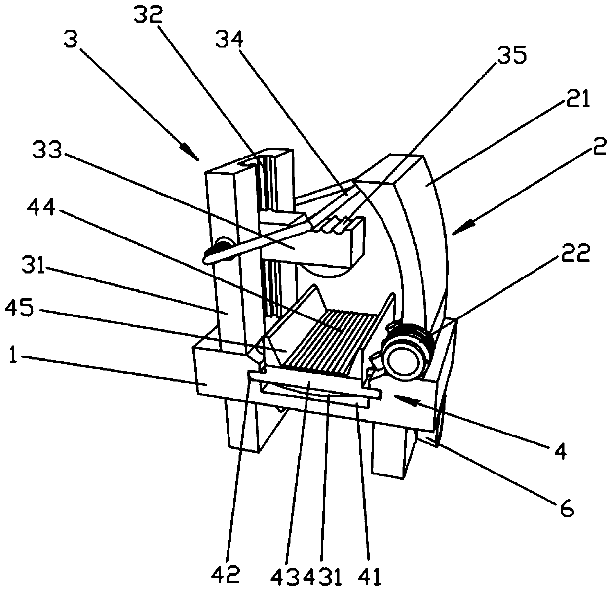
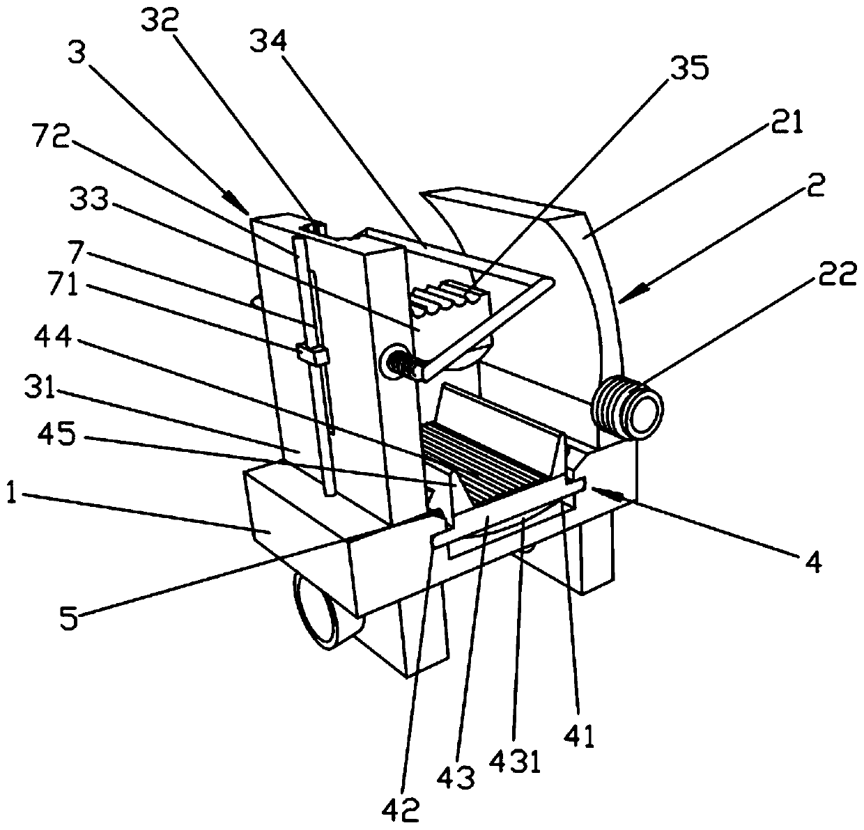
[0018] Such as Figure 1-2 As shown, it is a wire clamping device of a fault indicator in this embodiment, which includes a base 1, one end of the top surface of the base 1 is provided with a wire clamping device 2, and the other end of the top surface of the base 1 is provided with a wire clamping device 3, The wire device 2 includes an arc-shaped wire pressing plate 21, and one end of the arc-shaped wire pressing plate 21 is arranged on the top surface of the base 1 through a torsion spring 22, and the wire clamping device 3 includes a column plate 31, which is vertically arranged on the top surface of the base 1 The other end of the column plate 31 is provided with a guide groove 32 on the side wall of the column plate 31, and the guide groove 32 is opposite to the arc-shaped opening of the arc-shaped pressure line plate 21. Also be provided with U-...


PUM


Abstract

The invention, which relates to the technical field of circuit fault detection, provides a wire clamping and fixing device for a fault indicator. The wire clamping and fixing device comprises a pedestal. A wire pressing device is arranged at one end of the top surface of the pedestal; and a wire clamping device is arranged at the other end of the top surface of the pedestal. The wire pressing device includes an arc pressing plate; and one end of the arc pressing plate is arranged on the top surface of the pedestal by a torsional spring. The wire clamping device includes a standing column platearranged at the other end of the top surface of the pedestal vertically; a guide slot is formed in one side wall of the standing column plate, wherein the guide slot faces an arc opening of the arc pressing plate; and a clamping plate is arranged in the guide slot horizontally and movably. Besides, a U-shaped compression spring is also arranged on the standing column plate; and the two ends of the U-shaped opening of the U-shaped compression spring are arranged at the opposite side walls of the standing column plate respectively. A support gasket block device is also arranged on the top surface of the pedestal. The wire clamping and fixing device has advantages of firm structure, improved installation stability and firmness, simple operation and the like.

Description

technical field [0001] The invention relates to the technical field of circuit fault detection, in particular to a line clamping device for a fault indicator. Background technique [0002] Fault indicators in the prior art generally need to be installed on overhead lines or cables at higher positions. A fault indicator is a device used on overhead lines and power lines to detect and identify whether the power line is faulty. When short-circuit, grounding and other faults occur in the power line, the fault indicator determines the fault section, branch and fault point by detecting and judging the fault state, so as to facilitate the inspection and maintenance of the line patrol staff. Fault indicators in the prior art generally need to be installed on overhead lines or cables at higher positions. It needs to be installed on it with special equipment during installation. The Chinese patent number is ZL200320101371.6 invention patent, the announcement date is December 22, 200...

Claims


Application Information

Patent Timeline
IPC IPC(8): G01R1/04G01R31/08
Inventor 沈承刚
Owner HUAIAN HONGXIANG PHOTOELECTRIC TECH
Why Eureka
Try Eureka