
A Clutter Suppression Method Applicable to Slow Target Surveillance Radar

A technology for clutter suppression and surveillance radar, which is used in the use of re-radiation, radio wave measurement systems, and radio wave reflection/re-radiation to improve the detection signal-to-noise ratio, avoid resource loads, and improve clutter suppression capabilities.

Active Publication Date: 2021-02-23
重庆秦嵩科技有限公司
View PDF10 Cites 0 Cited by
  • Summary
  • Abstract
  • Description
  • Claims
  • Application Information

AI Technical Summary

Problems solved by technology

[0005] Aiming at the above-mentioned deficiencies in the prior art, the present invention provides a clutter suppression method suitable for slow target surveillance radars, which solves the false alarm and non-zero clutter caused by the remaining clutter without additional processing resources. The problem of background elevation of the filter improves the improvement factor and the signal-to-noise ratio of the system, which satisfies the detection performance of ground surveillance radars for slow and weak targets

Method used


Image

  • A Clutter Suppression Method Applicable to Slow Target Surveillance Radar
  • A Clutter Suppression Method Applicable to Slow Target Surveillance Radar
  • A Clutter Suppression Method Applicable to Slow Target Surveillance Radar

Examples


Embodiment 1

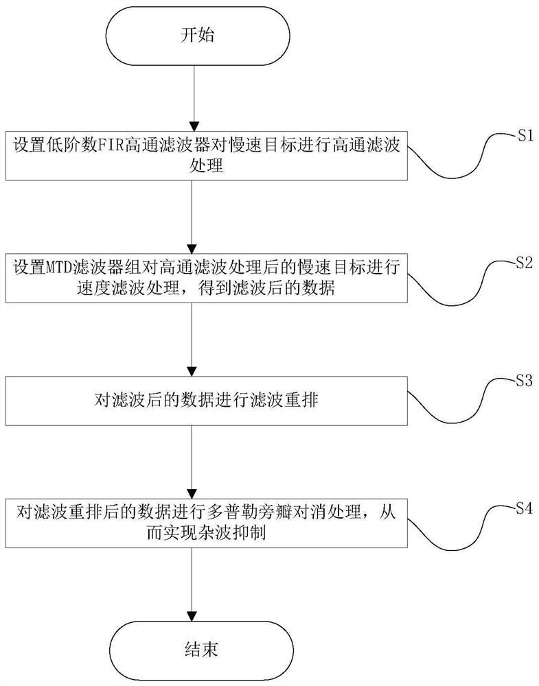
[0042] Such as figure 1 As shown, the present invention provides a kind of clutter suppression method that is applicable to slow target surveillance radar, and the specific steps of this method are as follows:

[0043] (S1) setting a low-order number FIR high-pass filter to carry out high-pass filter processing on the slow target;

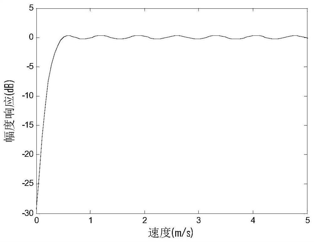
[0044] In order to avoid the resource load of the high-order FIR filter and the loss of radar range, a low-order filter is designed for the surveillance radar waveform, and high-pass filtering is performed on zero frequency and low frequency components near zero frequency. The spectral characteristics of clutter and the speed characteristics of slow targets, the filter stop band is designed to be 0m / s, such as figure 2 As shown, the passband design is 0.5m / s, and the order of the high-pass filter designed according to this method is 40. After passing through this filter, the zero-frequency clutter will be suppressed by about 27dB;

[0045] (S2) ...

Embodiment 2

[0071] Give another embodiment to further illustrate the present invention:

[0072] A Ku-band ground individual surveillance radar system is mainly aimed at the detection of border armed personnel. Its application scenarios include rocky mountains, forests and lakes and other strong clutter environments. The RCS of personnel is 0.5m 2 ~1m 2 , which is consistent with the detection characteristics of weak targets in the strong clutter background.

[0073] The parameters of some indicators of the radar are as follows:

[0074] Signal bandwidth: 30MHz;

[0075] Waveform repetition frequency: 3.125KHz;

[0076] Number of pulses: 256;

[0077] Minimum detectable target speed: 0.6m / s;

[0078] Maximum detectable distance for individual soldiers: not less than 8km;

[0079] Improvement factor: greater than 50dB (ground clutter: σ v = 0.3m / s).

[0080] For this system, the MTI+MTD+DSLC method is used for clutter suppression. Since the number of pulses is 256, a 60-order FIR f...


PUM


Abstract

The invention provides a clutter suppression method suitable for slow target surveillance radar, which includes the following steps: (S1) setting a low-order FIR high-pass filter to carry out high-pass filtering on a slow target; (S2) setting an MTD filter bank to carry out speed filtering on the slow target after high-pass filtering to obtain filtered data; (S3) carrying out filtering rearrangement on the filtered data; and (S4) carrying out Doppler sidelobe cancellation processing on the data after filtering rearrangement, so as to achieve clutter suppression. Through the design, the problems of false alarm and background elevation of a non-zero filter caused by clutter are solved without additional processing resources, the improvement factor and the system signal-to-clutter ratio are improved, and the detection performance of ground surveillance radar for slow and weak targets is satisfied. The method of the invention has the advantages of flexibility, high accuracy, small amount of calculation and good versatility, and is suitable for popularization and application.

Description

technical field [0001] The invention belongs to the technical field of radar signal processing, and in particular relates to a clutter suppression method suitable for a slow target surveillance radar. Background technique [0002] Generally speaking, ground clutter is a static echo, and its energy is concentrated near the zero Doppler frequency, which has the characteristics of bilateral symmetry. In the worst case, the root mean square spectrum width of the clutter is about 0.3m / s, and the intensity is usually 60-70dB higher than the thermal noise of the system. For the surveillance radar of low, small and slow targets, the target speed range of interest is often Extremely low, such as typical slow and weak targets such as individual soldiers, the speed range is 0.5-1.5m / s, and the radar effective reflection cross section is less than 1m 2 , in order to realize the effective detection of low-speed targets on the ground under such a high ground clutter background, the suppr...

Claims


Application Information

Patent Timeline
Patent Type & Authority Patents(China)
IPC IPC(8): G01S7/36G01S13/50
Inventor 陶晶
Owner 重庆秦嵩科技有限公司
Learn More