Light-emitting inductive switch structure for household electrical appliance
A technology for inductive switches and household appliances, applied in electrical switches, magnetic/electric field switches, circuits, etc., to solve problems such as users being unable to clearly identify the switch marks and troublesome for users to use.
- Summary
- Abstract
- Description
- Claims
- Application Information
AI Technical Summary
Problems solved by technology
Method used
Image

Examples
Embodiment 1
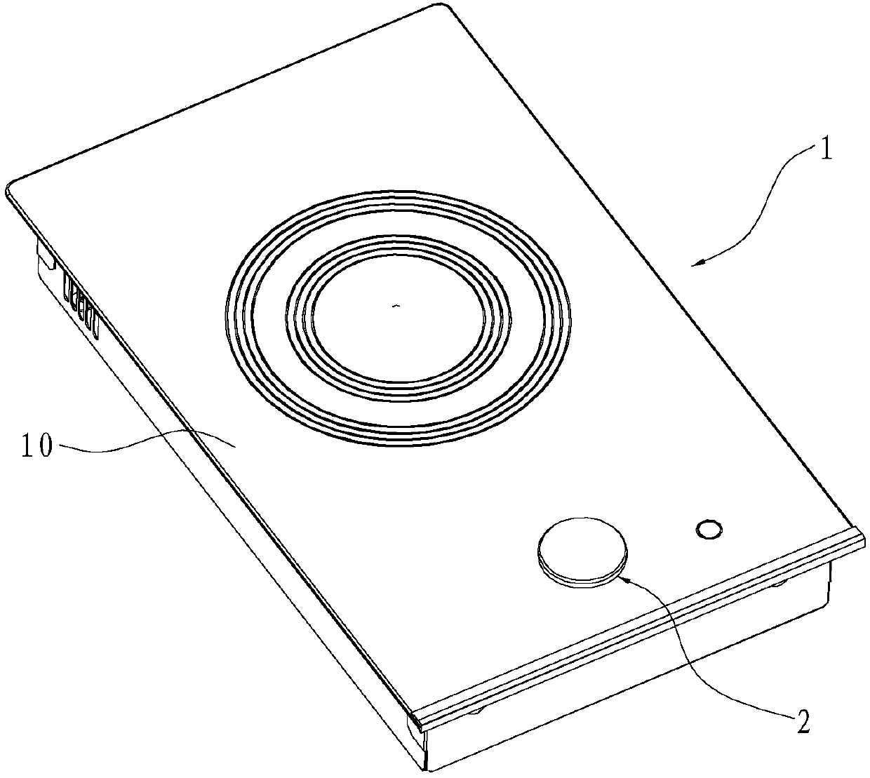
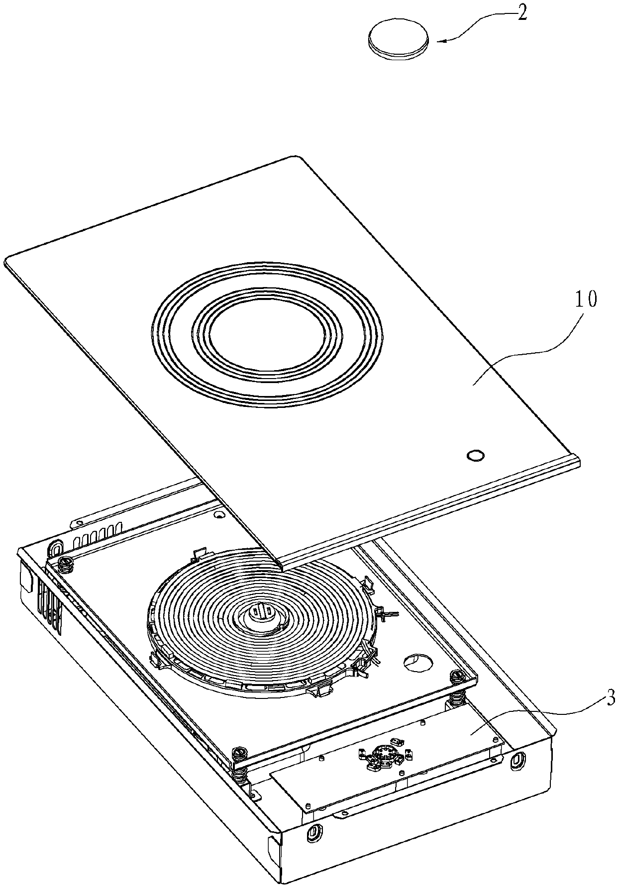
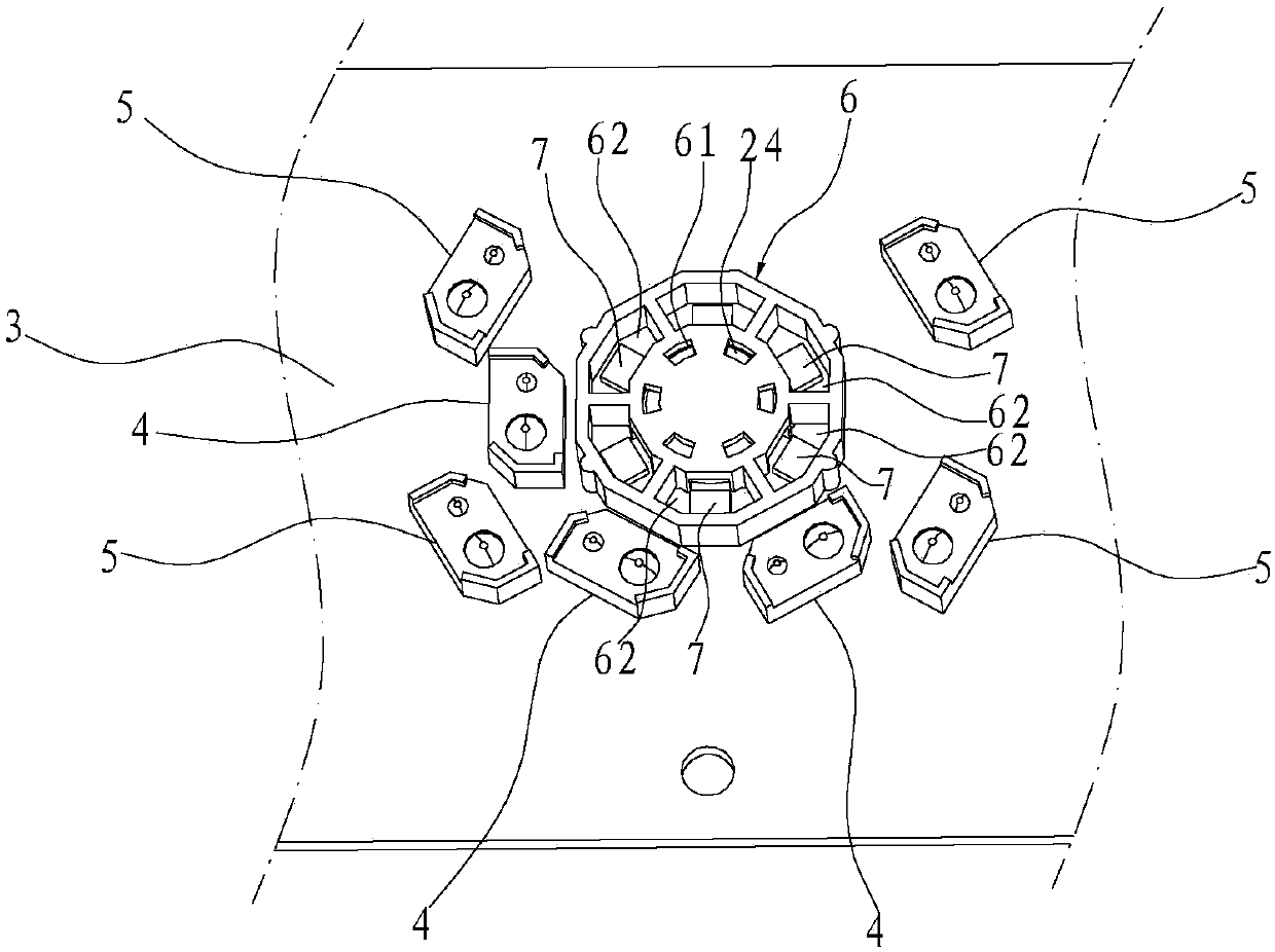
[0045] like Figure 1-11 As shown, a light-emitting induction switch structure used for household appliances, in this embodiment, the light-emitting induction switch structure is a magnetic induction switch knob applied to the electromagnetic cooker 1, which is arranged on the panel 10 of the electromagnetic cooker 1, including the The switch element 2 before 10 and the induction switch circuit board 3 arranged behind the panel 10, the panel 10 is a glass-ceramic panel. The first permanent magnet 23 is arranged in the above-mentioned switch part 2, and the second permanent magnet 24 is arranged on the inductive switch circuit board 3. mutual attraction to locate. In this embodiment, the switch part 2 is a knob part.
[0046]Further, the above-mentioned switch element 2 includes a circular upper cover 21 and a base 22, and is formed by the upper cover 21 and the base 22 being covered up and down, wherein the base 22 has a transparent bottom surface. In this embodiment, the a...
Embodiment 2
[0059] Such as Figure 12 As shown, the difference from Embodiment 1 is that in this embodiment, a light guide body 9 is provided at the above-mentioned second light guide surface 221, and the light emitted by the light source 7 is reflected by the first light guide surface 251 and then irradiates to the above-mentioned light guide surface. The light body 9 makes the light guide body 9 emit light, and then makes the third regulation area 21c emit light, and a circle of light is displayed on the switch member 2 . In this embodiment, the light guide body 9 is a ring, and is attached along the above-mentioned second light guide surface 221 .
Embodiment 3
[0061] Such as Figure 13-22 As shown, the difference from Embodiment 1 is that in this embodiment, the first optocoupler 4 corresponding to the first area has no electrical pulse signal output, while the first optocoupler 4 corresponding to the second area has an electrical pulse signal. Pulse signal output. Specifically, a light guide sheet 10 is arranged between the above-mentioned upper cover 21 and the sensor switch circuit board 3, and light guide grooves 101 extending in the radial direction are respectively arranged on the light guide sheet 10 corresponding to the above-mentioned first area, and the The included angle between the groove wall of the light guide groove 101 in the radial direction and the horizontal plane is 45° or 135°. The light guide grooves 101 are fan-shaped at 45°, and each light guide groove 101 is composed of light guide microgrooves 101a uniformly spaced along the circumferential direction, and the cross sections of the light guide microgrooves ...
PUM
 Abstract
Description
Claims
Application Information
 - R&D Engineer
- R&D Manager
- IP Professional
- Industry Leading Data Capabilities
- Powerful AI technology
- Patent DNA Extraction
Browse by: Latest US Patents, China's latest patents, Technical Efficacy Thesaurus, Application Domain, Technology Topic.
© 2024 PatSnap. All rights reserved.Legal|Privacy policy|Modern Slavery Act Transparency Statement|Sitemap