Cylinder clamping jaw for clamping-screwing warhead

A gripper and cylinder technology, which is applied to conveyor objects, transportation and packaging, etc., can solve the problems of twisted grippers, inability to clamp, and cannot be completed by manpower, so as to avoid twisting of grippers, improve stability, and achieve gripping. Effect

Inactive Publication Date: 2019-06-11
安徽玄离智能科技股份有限公司
View PDF12 Cites 10 Cited by
  • Summary
  • Abstract
  • Description
  • Claims
  • Application Information

AI Technical Summary

Problems solved by technology

[0002] Cylinder jaw is a device that realizes clamping and loosening through the expansion and contraction of the cylinder. With the continuous improvement of mechanized productivity, it is widely used in work and life. When clamping and handling certain materials, it often requires a larger It can only be done by force, but cannot be done by manpower at all. All of these need to be done by jaws, so the jaws are an indispensable device. In the use of fire-fighting shells, the structure of the jaws used to clamp and twist the warhead is complicated and cannot be effectively adapted to on job requirements;
[0003] There are certain disadvantages in the use of the existing cylinder jaws. First, the hinge between the existing connecting rod and the connecting arm is unstable, and it is impossible to maintain a stable connection between the connecting rod and the connecting arm at all times. The expansion and contraction of the rod is controlled by the limit, and the vertical expansion and contraction of the telescopic rod cannot be maintained. Due to the influence of distance, the clamping cannot be better realized, which has brought a certain impact on people's use process. Therefore, we propose a cylinder clamping jaw for clamping and twisting warheads.

Method used


Image

  • Cylinder clamping jaw for clamping-screwing warhead
  • Cylinder clamping jaw for clamping-screwing warhead
  • Cylinder clamping jaw for clamping-screwing warhead

Examples


Embodiment 1

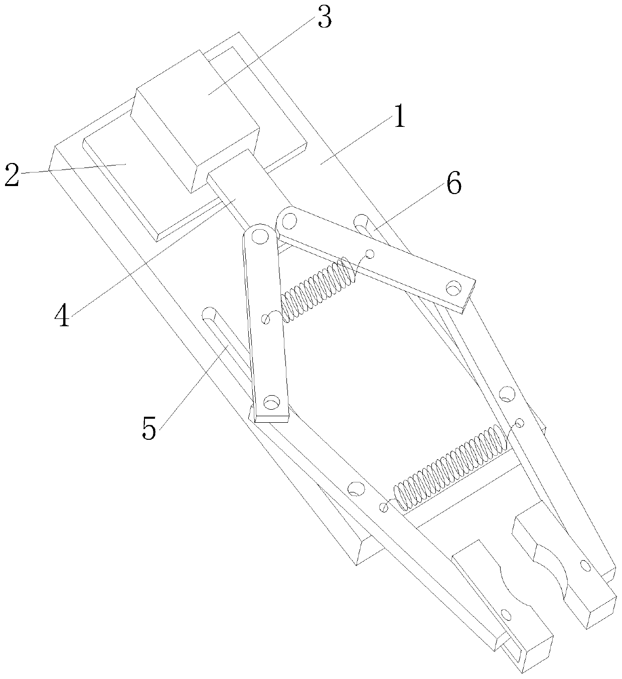
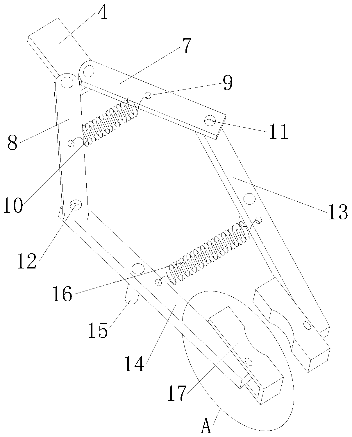
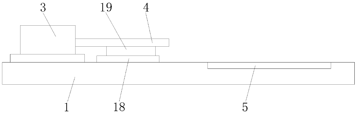
[0024] Such as Figure 1-4 As shown, a cylinder jaw for clamping and twisting warheads includes an installation base plate 1, a backing plate 2 is fixedly installed on one end of the upper side of the installation base plate 1, a cylinder 3 is fixedly installed on the upper end of the backing plate 2, and a telescopic Rod 4, the upper end of the telescopic rod 4 is movably connected to No. 1 connecting arm 7 and No. 2 connecting arm 8 through bolts, and one end of No. 1 connecting arm 7 is movably connected to No. 1 connecting rod 13 through No. 1 connecting shaft 11, and No. 2 connecting arm 8 One end of one end is connected with No. 2 connecting rod 14 through No. 2 connecting shaft 12, and the middle positions of No. 1 connecting arm 7, No. 2 connecting arm 8, No. 1 connecting rod 13 and No. 2 connecting rod 14 are provided with clamping holes 9. A No. 1 spring 10 is connected between the clamping hole 9 on the No. 1 connecting arm 7 and the No. 2 connecting arm 8 , and a N...

Embodiment 2

[0027] Such as Figure 1-4 As shown, a cylinder jaw for clamping and twisting warheads includes an installation base plate 1, a backing plate 2 is fixedly installed on one end of the upper side of the installation base plate 1, a cylinder 3 is fixedly installed on the upper end of the backing plate 2, and a telescopic Rod 4, the upper end of the telescopic rod 4 is movably connected to No. 1 connecting arm 7 and No. 2 connecting arm 8 through bolts, and one end of No. 1 connecting arm 7 is movably connected to No. 1 connecting rod 13 through No. 1 connecting shaft 11, and No. 2 connecting arm 8 One end of one end is connected with No. 2 connecting rod 14 through No. 2 connecting shaft 12, and the middle positions of No. 1 connecting arm 7, No. 2 connecting arm 8, No. 1 connecting rod 13 and No. 2 connecting rod 14 are provided with clamping holes 9. A No. 1 spring 10 is connected between the clamping hole 9 on the No. 1 connecting arm 7 and the No. 2 connecting arm 8 , and a N...

Embodiment 3

[0032] Such as Figure 1-4 As shown, a cylinder jaw for clamping and twisting warheads includes an installation base plate 1, a backing plate 2 is fixedly installed on one end of the upper side of the installation base plate 1, a cylinder 3 is fixedly installed on the upper end of the backing plate 2, and a telescopic Rod 4, the upper end of the telescopic rod 4 is movably connected to No. 1 connecting arm 7 and No. 2 connecting arm 8 through bolts, and one end of No. 1 connecting arm 7 is movably connected to No. 1 connecting rod 13 through No. 1 connecting shaft 11, and No. 2 connecting arm 8 One end is connected with No. 2 connecting rod 14 through No. 2 connecting shaft 12,

[0033] The two sides of the upper end of the installation base plate 1 are respectively provided with No. 1 chute 5 and No. 2 chute 6, and No. 1 chute 5 is located at the lower end of No. 2 connecting arm 8 and No. 2 connecting rod 14, and No. 2 chute 6 is located at No. 1 The lower ends of the conne...


PUM


Abstract

The invention discloses a cylinder clamping jaw of a clamping-screwing warhead. The cylinder clamping jaw comprises a mounting bottom plate, a backing plate is fixedly mounted at one end of the upperside of the mounting bottom plate, a cylinder is fixedly mounted at the upper end of the backing plate, a telescopic rod is arranged at the front end of the cylinder, and a first connecting arm and asecond connecting arm are movably connected to the upper end of the telescopic rod through bolts. The cylinder clamping jaw of the clamping-screwing warhead can improve the stability of the hinge connection between connecting rods and the connecting arms, the stable connection between the connecting rods and the connecting arms is maintained at all times, the extension and contraction of the telescopic rod can be limited and controlled, the vertical extension and contraction of the telescopic rod are maintained to avoid the distortion of a clamping jaw caused by the bending of extension and contraction of the telescopic rod under the action of external force, a groove is formed in one end of the clamping jaw and movably connected with a first connecting rod and a second connecting rod through rotating shafts, so that the clamping jaw can be flexibly clamped, the bottom ends of the first connecting rod and the second connecting rod abut against the inner wall of the groove, the clampingjaw is not affected by the size of a clamped object, so that the clamping is better realized.

Description

technical field [0001] The invention relates to the field of cylinder jaws, in particular to a cylinder jaw for clamping and twisting warheads. Background technique [0002] Cylinder jaw is a device that realizes clamping and loosening through the expansion and contraction of the cylinder. With the continuous improvement of mechanized productivity, it is widely used in work and life. When clamping and handling certain materials, it often requires a larger It can only be done by force, but cannot be done by manpower at all. All of these need to be done by jaws, so the jaws are an indispensable device. In the use of fire-fighting shells, the structure of the jaws used to clamp and twist the warhead is complicated and cannot be effectively adapted to on job requirements; [0003] There are certain disadvantages in the use of the existing cylinder jaws. First, the hinge between the existing connecting rod and the connecting arm is unstable, and it is impossible to maintain a st...

Claims


Application Information

Patent Timeline
IPC IPC(8): B65G47/91
Inventor 郭延达
Owner 安徽玄离智能科技股份有限公司
Why Eureka
Try Eureka