Control device for selectable one-way clutch
A technology of one-way clutches and control devices, which is applied in one-way clutches, clutches, mechanical equipment, etc., can solve problems such as support parts impacting support part abnormalities, and achieve the effect of preventing failures and suppressing abnormalities
- Summary
- Abstract
- Description
- Claims
- Application Information
AI Technical Summary
Problems solved by technology
Method used
Image
Examples
Embodiment 1
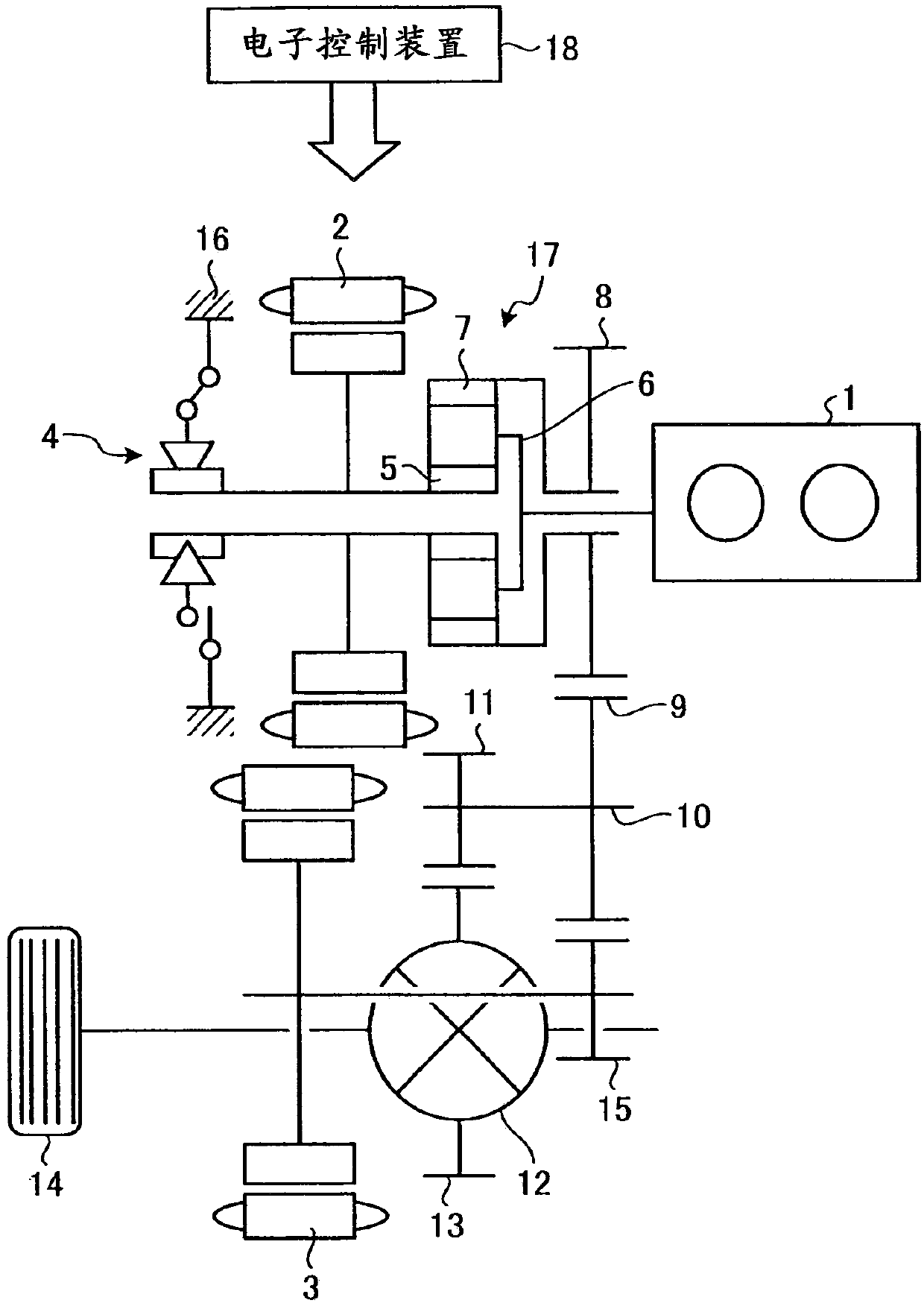
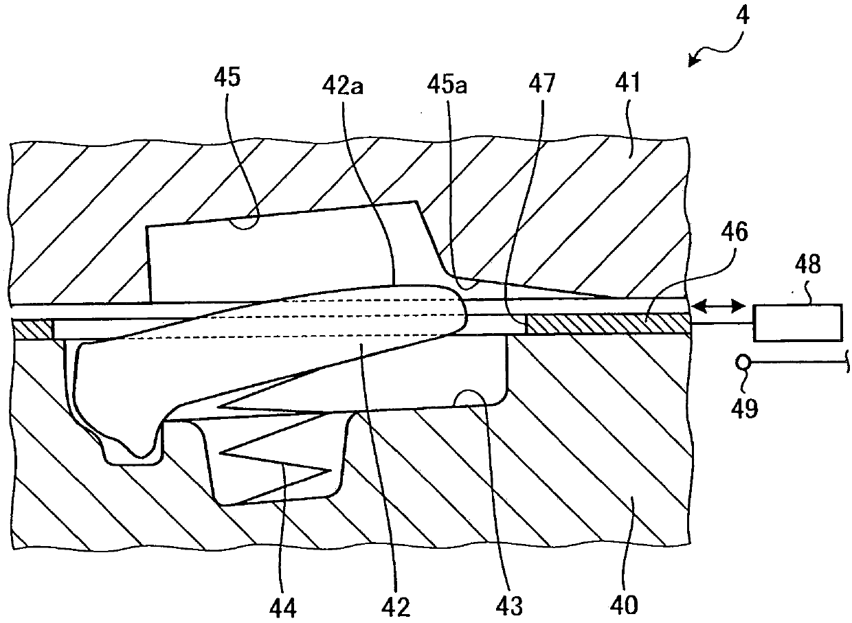
[0077] Figure 4 It is a graph showing the relationship between the vehicle speed V and the rotation speed Ns of the SOWC 4 in the first embodiment. In addition, in Figure 4 Among them, Ne is the speed of the engine 1 , Ne_idle is the idle speed of the engine 1 , Ne_start is the maximum speed of the engine 1 when the engine starts, and Ne_max is the maximum speed of the engine 1 . In addition, in Figure 4 Among them, Ns is the speed of SOWC4, Ns_ratchet is the minimum speed of SOWC4 that can avoid engagement even if the ratchet state is maintained, Ns_infinite - It is the minimum rotational speed of SOWC4 that can ensure an infinite life of the support 42 for an infinite period without damage or a semi-infinite life of the support 42 as long as the life of the vehicle even if the overtravel state continues. In addition, in Figure 4 in, V 1 is the vehicle speed when the rotation speed Ns of the SOWC 4 is 0 [rpm] and the rotation speed Ne of the engine 1 is the maximum r...
Embodiment 2
[0086] Image 6 It is a graph showing the relationship between the vehicle speed V and the rotation speed Ns of the SOWC 4 in the second embodiment. In addition, in Image 6 In, Ns_infinite + It is the maximum rotation speed of SOWC4 that can ensure infinite life or semi-infinite life even if the ratchet state is maintained. In addition, in Image 6 in, V 3 is the speed Ns of SOWC4 is Ns_infinite + In addition, the rotational speed Ne of the engine 1 is the vehicle speed at the idle rotational speed Ne_idle.
[0087] Figure 7 is shown based on Image 6 A flow chart of failure control in Embodiment 2 implemented based on the relationship between the vehicle speed V and the rotation speed Ns of the SOWC4 shown. When the vehicle is running, execute this function repeatedly every specified short time. Figure 7 The routine for fault control is shown.
[0088] First, when running in the released state of the SOWC4, the electronic control unit 18 determines whether the se...
Embodiment 3
[0095] Figure 8 It is a graph showing the relationship between the vehicle speed V and the rotation speed Ns of the SOWC4 in the third embodiment. In addition, in Figure 8 In, Ns_finite + It is the maximum rotational speed of the SOWC 4 that can ensure a limited life span in which the support 42 is not damaged for a limited period of time even if the ratchet state is maintained. Figure 9 is shown based on Figure 8A flow chart of failure control in Embodiment 3 implemented based on the shown relationship between the vehicle speed V and the rotational speed Ns of the SOWC4. When the vehicle is running, execute this function repeatedly every specified short time. Figure 9 The routine for fault control is shown.
[0096] First, when running in the released state of the SOWC4, the electronic control unit 18 determines whether the sensor 49 has detected an unexpected stroke of the actuator 48 caused by an unexpected operation of the selector plate 46 (step S41). When it i...
PUM
 Abstract
Description
Claims
Application Information
 - R&D
- Intellectual Property
- Life Sciences
- Materials
- Tech Scout
- Unparalleled Data Quality
- Higher Quality Content
- 60% Fewer Hallucinations
Browse by: Latest US Patents, China's latest patents, Technical Efficacy Thesaurus, Application Domain, Technology Topic, Popular Technical Reports.
© 2025 PatSnap. All rights reserved.Legal|Privacy policy|Modern Slavery Act Transparency Statement|Sitemap|About US| Contact US: help@patsnap.com


