
Touch display panel and touch display device

A technology for a touch display panel and display area, which is applied in the fields of instruments, computing, electrical and digital data processing, etc., can solve the problems of reducing the capacitance value, reducing the touch sensitivity of the touch display panel, and increasing the resistance value, etc.

Active Publication Date: 2019-06-11
YUNGU GUAN TECH CO LTD
View PDF5 Cites 11 Cited by
  • Summary
  • Abstract
  • Description
  • Claims
  • Application Information

AI Technical Summary

Problems solved by technology

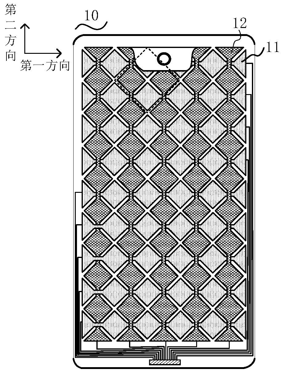
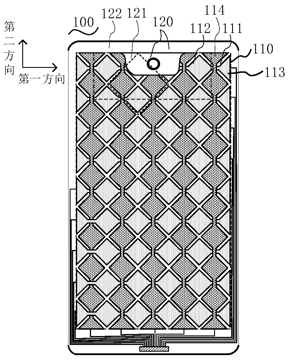
[0003] However, in the prior art, when the touch display panel is dug out to embed the grooved area of ​​functional modules such as cameras, part of the electrodes of the touch driving electrodes and touch sensing electrodes of the touch panel are usually missing. However, the resistance value of the touch driving electrode or touch sensing electrode missing part of the electrode will increase, while the capacitance value will decrease, which will lead to the weakening of the touch signal transmitted by the touch electrode and reduce the performance of the touch display panel. Touch Sensitivity

Method used


Image

  • Touch display panel and touch display device
  • Touch display panel and touch display device
  • Touch display panel and touch display device

Examples


Embodiment Construction

[0026] In order to make the purpose, technical solution and advantages of the present application clearer, the present application will be further described in detail below in conjunction with the accompanying drawings and embodiments. It should be understood that the specific embodiments described here are only used to explain the present application, and are not intended to limit the present application.

[0027] It should be noted that when an element is referred to as being “disposed on” another element, it may be directly on the other element or there may also be an intervening element. When an element is referred to as being "connected to" another element, it can be directly connected to the other element or intervening elements may also be present. The terms "vertical," "horizontal," "left," "right," and similar expressions are used herein for purposes of illustration only and are not intended to represent the only embodiments.

[0028] Unless otherwise defined, all te...


PUM


Abstract

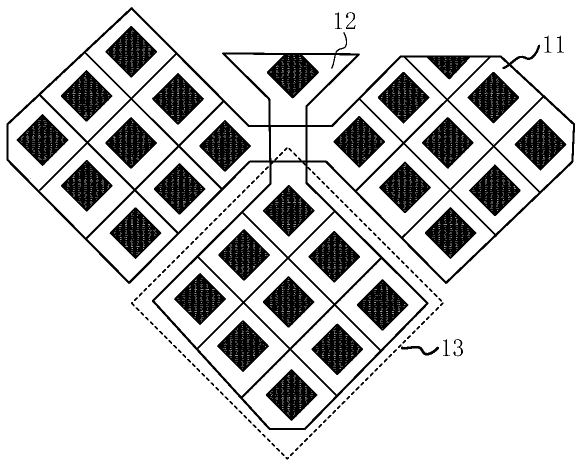
The invention relates to a touch display panel and a touch display device. The touch display panel comprises a display area and a non-display area surrounding the display area. the non-display area comprises at least one grooving area arranged at any position around the display area; the display area comprises a first display area and a second display area, the second display area is located between the first display area and the grooving area, the first display area and the second display area comprise a plurality of induction electrodes arranged in the first direction and a plurality of driving electrodes arranged in the second direction, and the induction electrodes and the driving electrodes are arranged in a mutually crossed and insulated mode; Wherein the sensing electrode and / or thedriving electrode comprise / comprises a plurality of electrode units, and each electrode unit comprises an electrode pattern and at least one dummy pattern; And the virtual patterns of the electrode units in the second display area are electrically connected with the electrode patterns. According to the touch display panel, by increasing the area of the electrode pattern in the second display area, the touch sensitivity of the display area near the grooving area of the touch display panel is effectively improved.

Description

technical field [0001] The present invention relates to the field of touch display, in particular to a touch display panel and a touch display device. Background technique [0002] With the rapid development of display technology, touch display technology has gradually pervaded people's lives. Among the existing touch display panels, the capacitive touch display panel has the advantages of long life, high light transmittance, multi-touch support, etc., and has become a hot spot of touch display technology. In recent years, in order to meet the diverse needs of people, the existing touch display panels usually need to cut the edge, for example, dig a certain area of ​​slotting area on the upper edge of the touch display panel, and in the slotting area Embed functional modules such as cameras. [0003] However, in the prior art, when the touch display panel is dug out to embed the grooved area of ​​functional modules such as cameras, part of the electrodes of the touch drivi...

Claims


Application Information

Patent Timeline
IPC IPC(8): G06F3/044G06F3/041
Inventor 程芸
Owner YUNGU GUAN TECH CO LTD
Learn More