lift bed frame

A bed frame and frame technology, applied in the field of lifting bed frames, can solve the problems of reducing the service life of bed and floor decoration, affecting work efficiency and work quality, and damage to bed and floor decoration, etc., to achieve convenient cleaning work, simple and stable connection structure , the effect of prolonging the service life

Active Publication Date: 2021-12-31
陈庆芳
View PDF15 Cites 0 Cited by
  • Summary
  • Abstract
  • Description
  • Claims
  • Application Information

AI Technical Summary

Problems solved by technology

Considering the beauty of the display and the convenience of use, the beds are usually placed against the wall, and the bottom space of the bed is low, so it is very inconvenient to make the bed and clean the room
When changing sheets and bedding, make the bed so that the end that touches the wall is away from the wall; cleaning the bottom of the bed requires freeing up the floor under the bed and moving the bed as a whole, which is very inconvenient
If the bottom of the bed is not cleaned frequently, a lot of dust and flocculent fibers will often be deposited, which will become a breeding ground for bacteria and pests.
Especially in the environment of hotels and hotels, it is necessary to tidy up a large number of guest rooms every day, and move the bulky beds as a whole
Laying and arranging sheets and bedding, and cleaning the bottom of the bed have become the most time-consuming and laborious tasks for the service staff to clean the guest room, which not only affects work efficiency and work quality, but also frequently moves the bed and easily damages the bed and floor decoration (carpet and floor paint). Damage, reducing the lifespan of beds and floor finishes

Method used


Image

  • lift bed frame
  • lift bed frame
  • lift bed frame

Examples


Embodiment Construction

[0018] The following will clearly and completely describe the technical solutions in the embodiments of the present invention with reference to the accompanying drawings in the embodiments of the present invention. Obviously, the described embodiments are only some, not all, embodiments of the present invention. Based on the embodiments of the present invention, all other embodiments obtained by persons of ordinary skill in the art without creative work, any modifications, equivalent replacements, improvements, etc., shall be included in the protection scope of the present invention Inside.

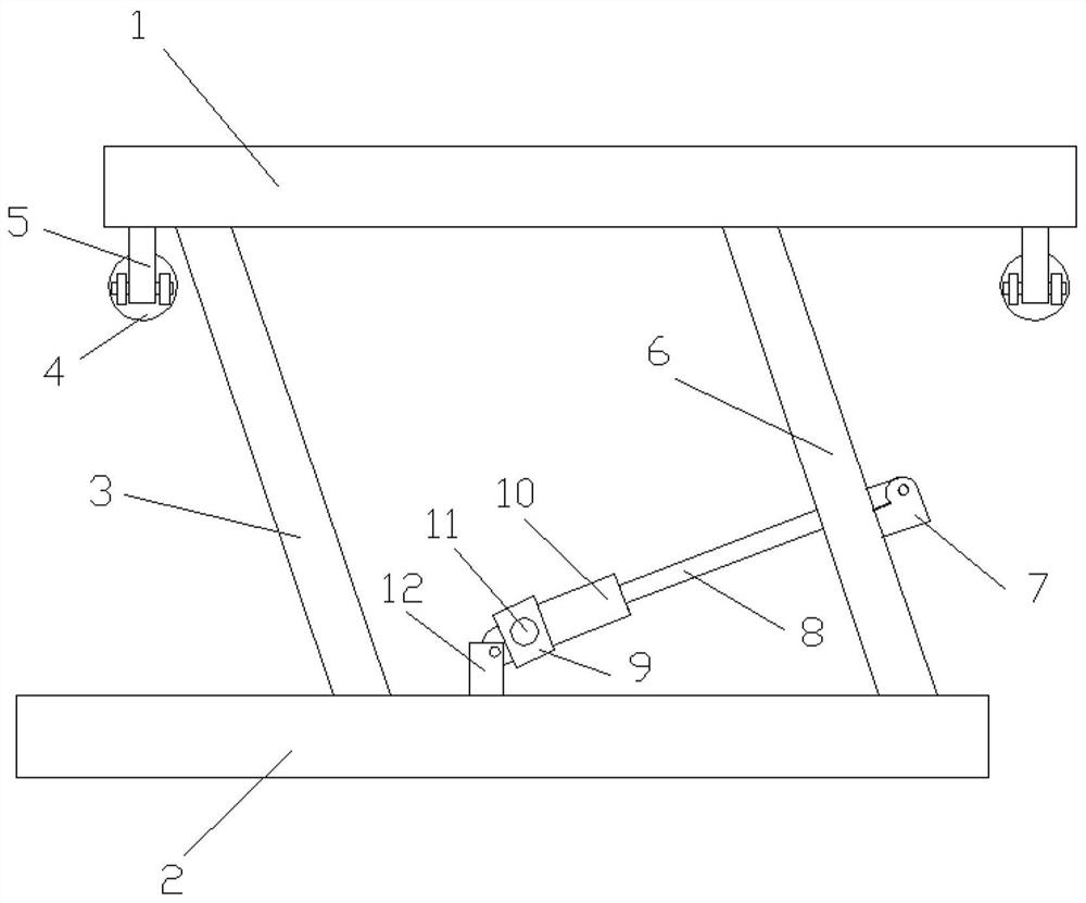
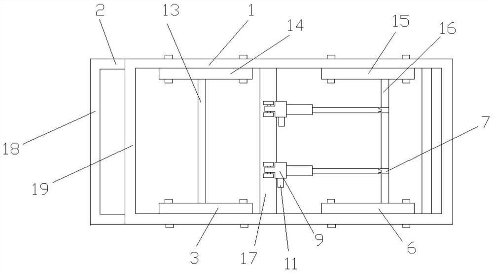
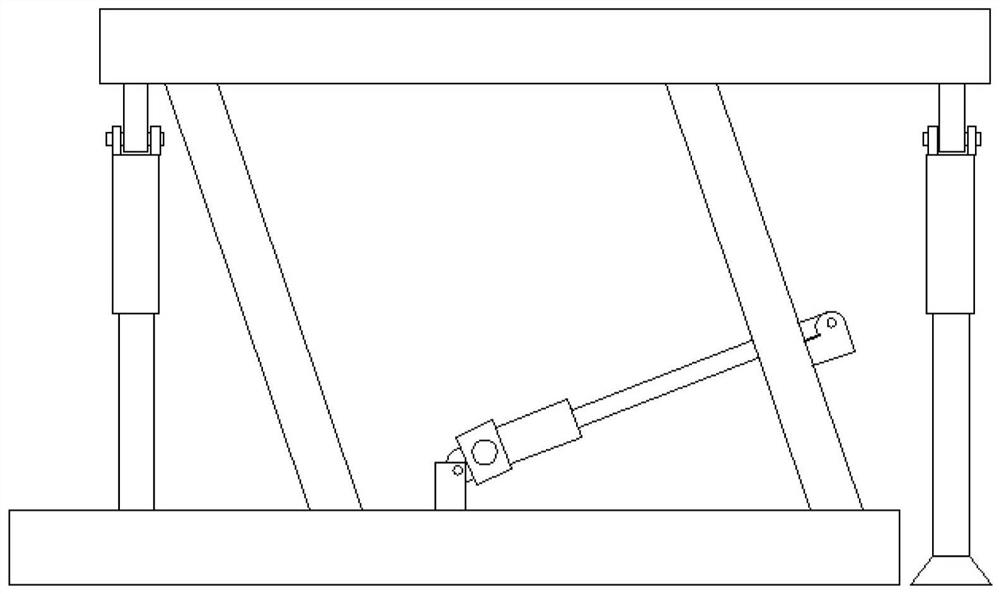
[0019] Such as Figure 1 to Figure 5 As shown, a lifting bed frame includes an upper frame and a lower frame, a mattress is placed on the upper frame, and the upper frame is movably connected with the lower frame. , two first horizontal long tubes 1 and two first vertical short tubes 19 are welded to form a rectangular upper frame; the lower frame includes a second horizontal long tube 2...


PUM


Abstract

The invention discloses an elevating bed frame, which comprises an upper frame and a lower frame, the upper frame is movably connected with the lower frame, the upper frame includes a first long horizontal tube and a first short vertical tube; the lower frame includes a second long horizontal tube, a second long tube Two longitudinal short tubes; the inner sides of the front ends of the two first horizontal long tubes of the upper frame are connected with the inner pin shafts of the front ends of the two second horizontal long tubes of the lower frame through the first support rod and the second support rod. The middle parts of the two support rods are welded through the first connecting rod; the inner sides of the front ends of the two first horizontal long tubes of the upper frame are connected with the inner pins of the front ends of the two second horizontal long tubes of the lower frame through the first support rod and the second support rod, The middle part of the third support rod and the fourth support rod is welded by the second connecting rod; the middle part of the two second transverse long tubes of the lower frame is welded with the third connecting rod, and the pin shaft between the first connecting rod and the third connecting rod is connected to the turbine. The screw rod lifting assembly; the lower end surface of the upper frame is connected with a lifting column.

Description

technical field [0001] The invention relates to the field of daily life, in particular to an elevating bed frame. Background technique [0002] Simmons beds are usually used in hotels now. These beds consist of a bed frame with a Simmons mattress and headboard resting on top of it. Considering the beauty of the decoration and the convenience of use, the beds are usually placed against the wall, and the bottom space of the bed is low, so it is very inconvenient to arrange the bed and clean the room. To change the bed sheets and bedding and make the bed, the end that touches the wall must be separated from the wall; to clean the bottom of the bed, the floor under the bed must be vacated, and the bed must be moved as a whole, which is very inconvenient. If the bottom of the bed is not cleaned frequently, a lot of dust and flocculent fibers will often be deposited, which will become a breeding ground for bacteria and pests. Especially in the environment of hotels and hotels, ...

Claims


Application Information

Patent Timeline
Patent Type & Authority Patents(China)
IPC IPC(8): A47C19/04
Inventor 陈庆芳
Owner 陈庆芳
Why Eureka
Try Eureka