Novel skin traction device and assembly method thereof

A new type of skin traction technology, applied in the field of new skin traction devices and their assembly, can solve the problems of inability to achieve fast lower limb skin traction, difficult to adjust traction posture, and local tissue pain, so as to avoid the phenomenon of skin traction falling off, avoid Effects of edema and reduction of transport space

Inactive Publication Date: 2019-06-14
HANGZHOU FIRST PEOPLES HOSPITAL
View PDF1 Cites 3 Cited by
  • Summary
  • Abstract
  • Description
  • Claims
  • Application Information

AI Technical Summary

Problems solved by technology

[0003] While the existing lower limb skin traction plays a therapeutic role, it is prone to slipping during the traction process, and additional traction counterweights are needed to provide traction. For example, Chinese patent CN201520301943.8 discloses an anti-falling lower limb skin traction The device consists of a thigh pad, a calf pad, a drawstring, an air tube, an adhesive tape, a belt buckle, a support plate and a hook, and the air tube is arranged on the thigh pad and the calf pad, and between the thigh pad and the calf pad It is connected by a drawstring. There are adhesive tapes on one side of the thigh pad and the calf pad. A support plate is provided on the drawstring under the calf pad. There is a belt buckle on the drawstring between the pads; this design only solves the firmness of the fixation and increases comfort, but it still needs external traction parts during the traction process, which cannot achieve fast lower limb skin traction, and it is difficult to adjust after traction Traction posture, patients in the same traction posture for a long time can easily cause local tissue soreness and edema. Therefore, we propose a new type of skin traction device and its assembly method

Method used


Image

  • Novel skin traction device and assembly method thereof
  • Novel skin traction device and assembly method thereof
  • Novel skin traction device and assembly method thereof

Examples


Embodiment Construction

[0036] The present invention will be further described below in conjunction with the accompanying drawings.

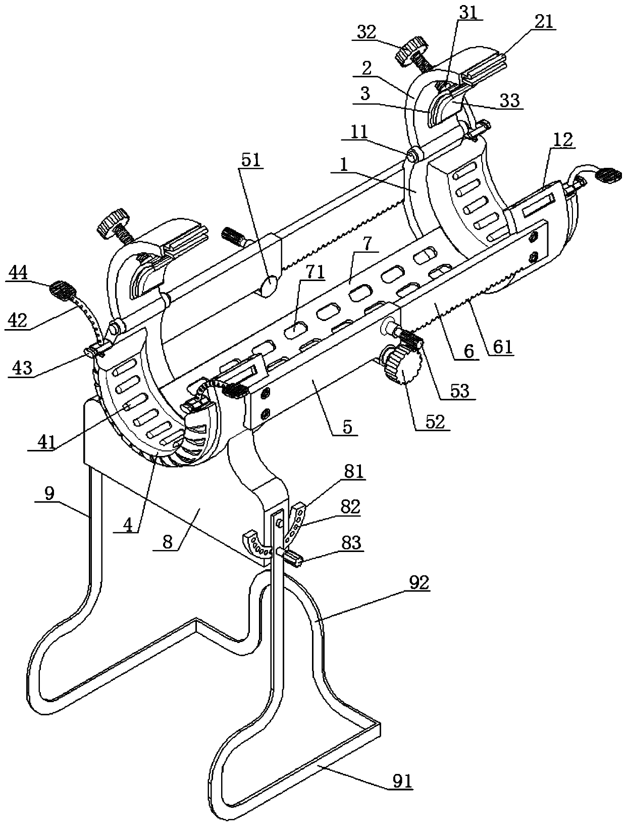
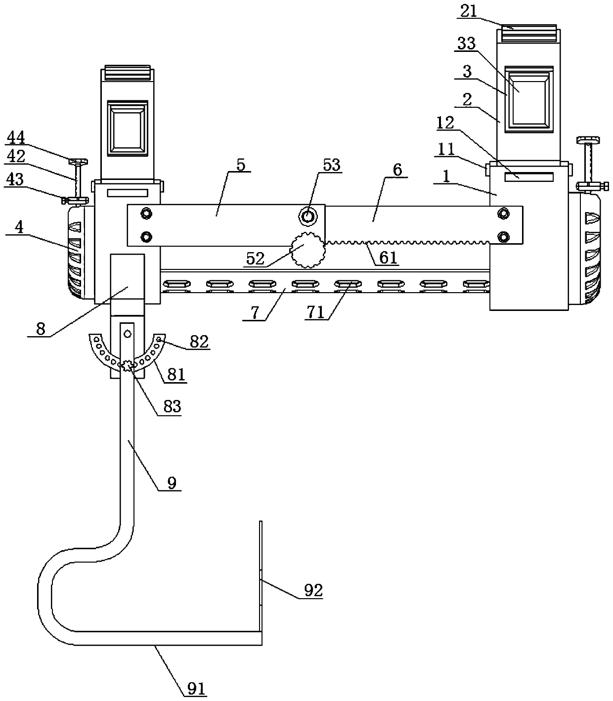
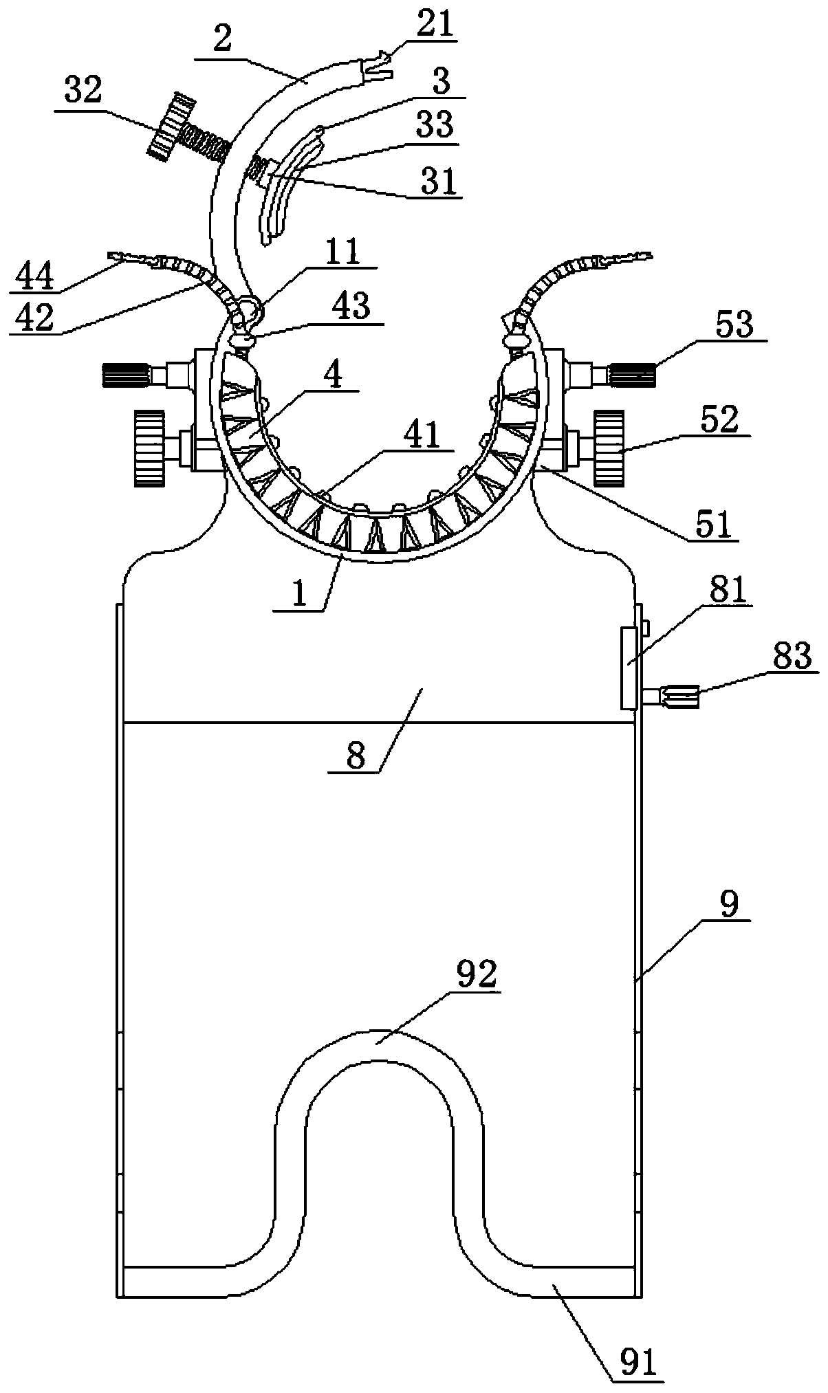
[0037] Such as Figures 1 to 3 The new skin traction device shown includes an ankle rest and a knee rest. The ankle rest and the knee rest have the same structure and are arranged symmetrically. The size of the knee rest is larger than that of the ankle rest. The ankle rest is used to fix the ankle of the affected limb. Joint, the knee rest is used to fix the knee joint of the affected limb.

[0038] Both the ankle rest and the knee rest include a bracket 1 with an arc-shaped structure, and one side of the bracket 1 is connected to a cover plate 2 with an arc-shaped structure through a pin shaft 11, and a clamping mechanism is fixed on the cover plate 2. The clamping mechanism includes a splint 3 with an arc structure. The splint 3 is arranged on the inner arc side of the cover plate 2. A shaft sleeve 31 is fixed in the middle of one side of the splint 3 corresponding t...


PUM


Abstract

The invention discloses a novel skin traction device, which comprises an ankle holding part and a knee holding part. The ankle holding part and the knee holding part have a same structure, the ankle holding part and the knee holding part comprise brackets, and one side of the brackets are connected with a cover plate through rotation of a pin, a clamping mechanism is fixed on the cover plate, anda buckling mechanism is arranged between one end of the cover plate away from the pin and the bracket, a lower cushion is fixed on the inner wall of the bracket, the outer edge of the lower cushion isprovided with a tightening mechanism, adjustable support arms are arranged between the ankle holding part and the knee holding part on both sides, an elastic support strap is fixedly connected to thebottom between the ankle holding part and the knee holding part, and the bottom end of the ankle holding part is fixedly provided with a supporting mechanism. By providing the adjustable support armsbetween the ankle holding part and the knee holding part, rapid skin traction is achieved with ensuring of no traction falling, through the supporting mechanism, the adjustment of a traction supportangle can be realized, and the tissue pain and edema phenomenon caused by the long-term traction at a same posture can be avoided.

Description

technical field [0001] The invention relates to the field of medical care equipment, in particular to a novel leather traction device and an assembly method thereof. Background technique [0002] Lower extremity skin traction is an indispensable non-invasive treatment tool in the treatment of orthopedic patients. Its function is mainly to use traction and counter traction to act on the fracture to achieve the purpose of reduction or maintenance of reduction and fixation. [0003] While the existing lower limb skin traction plays a therapeutic role, it is prone to slipping during the traction process, and additional traction counterweights are needed to provide traction. For example, Chinese patent CN201520301943.8 discloses an anti-falling lower limb skin traction The device consists of a thigh pad, a calf pad, a drawstring, an air tube, an adhesive tape, a belt buckle, a support plate and a hook, and the air tube is arranged on the thigh pad and the calf pad, and between th...

Claims


Application Information

Patent Timeline
Patent Type & Authority Applications(China)
IPC IPC(8): A61F5/042
Inventor 胡炜杨湘英朱明丽朱英夏柳勤马建萍
Owner HANGZHOU FIRST PEOPLES HOSPITAL
Why Eureka
Try Eureka