

Spanner with detachable ejector header
A technology for holding rods and linkage rings, which is applied to wrenches, manufacturing tools, wrenches, etc. It can solve the problems of insufficient disassembly force, unstable work efficiency of plug disassembly, uneven quality of pipe wrench, etc., and achieves convenient change and adjustment Effect
- Summary
- Abstract
- Description
- Claims
- Application Information
AI Technical Summary
Problems solved by technology
Method used
Image

Examples
Embodiment 1
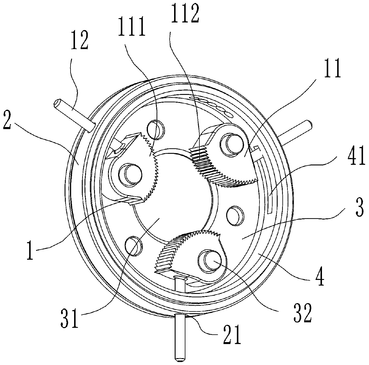
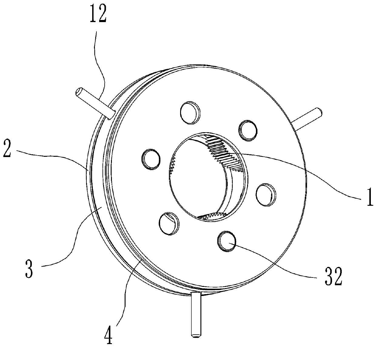
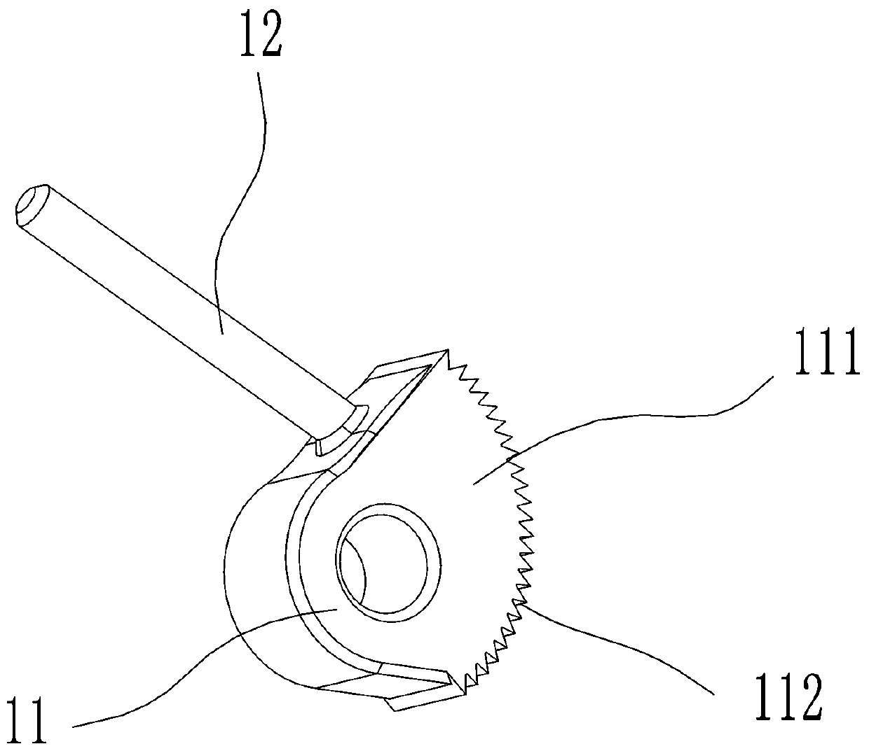
[0035] Embodiment one, such as figure 1 , 2 , 3, 4 and 5, a wrench for head disassembly includes a clamping part 1, a linkage ring 2 and a mounting panel 3, the clamping part 1 includes a clamping wheel 11 and a gripping rod 12, the clamping The holding wheel 11 is connected to the holding rod 12, the linkage ring 2 is provided with a connecting hole 21, the holding rod 12 is connected to the linkage ring 2 through the connecting hole 21, and the mounting panel 3 is A through hole 31 and a mounting column 32 are provided, and the clamping part 1 is connected to the mounting panel 3 through the mounting column 32 . At least one layer of abutting portion 111 is provided on the surface of the clamping wheel 11, and the width of at least one section of the abutting portion 111 gradually increases, and the abutting portion 111 is fixedly connected to the clamping wheel 11 or integrated connection, the width of the abutting portion 111 increases sequentially, and the width of the ...
Embodiment 2
[0037] Embodiment two, such as figure 1 , 2 , 3, 4 and 5, a wrench for head disassembly includes a clamping part 1, a linkage ring 2 and a mounting panel 3, the clamping part 1 includes a clamping wheel 11 and a gripping rod 12, the clamping The holding wheel 11 is connected to the holding rod 12, the linkage ring 2 is provided with a connecting hole 21, the holding rod 12 is connected to the linkage ring 2 through the connecting hole 21, and the mounting panel 3 is A through hole 31 and a mounting column 32 are provided, and the clamping part 1 is connected to the mounting panel 3 through the mounting column 32 . At least one layer of abutting portion 111 is provided on the surface of the clamping wheel 11, and the width of at least one section of the abutting portion 111 gradually increases, and the abutting portion 111 is fixedly connected to the clamping wheel 11 or integrated connection, the width of the abutment portion 111 increases sequentially, and the width of the ...
PUM
 Abstract
Description
Claims
Application Information