Vehicle control system, vehicle control method, and storage medium

一种车辆控制系统、车辆的技术,应用在控制装置、车辆部件、混合动力车辆等方向,能够解决发电机构运转的时机考虑、发电部不运转等问题,达到缓和不安的效果

Active Publication Date: 2019-06-14
HONDA MOTOR CO LTD
View PDF8 Cites 3 Cited by
  • Summary
  • Abstract
  • Description
  • Claims
  • Application Information

AI Technical Summary

Problems solved by technology

[0003] However, like the above-mentioned vehicles, there are cases where the timing of operating the power generating mechanism is not taken into consideration.
Therefore, there is a case where the power generation unit does not operate at a timing intended by the user.

Method used


Image

  • Vehicle control system, vehicle control method, and storage medium
  • Vehicle control system, vehicle control method, and storage medium
  • Vehicle control system, vehicle control method, and storage medium

Examples


no. 1 approach

[0041] [the whole frame]

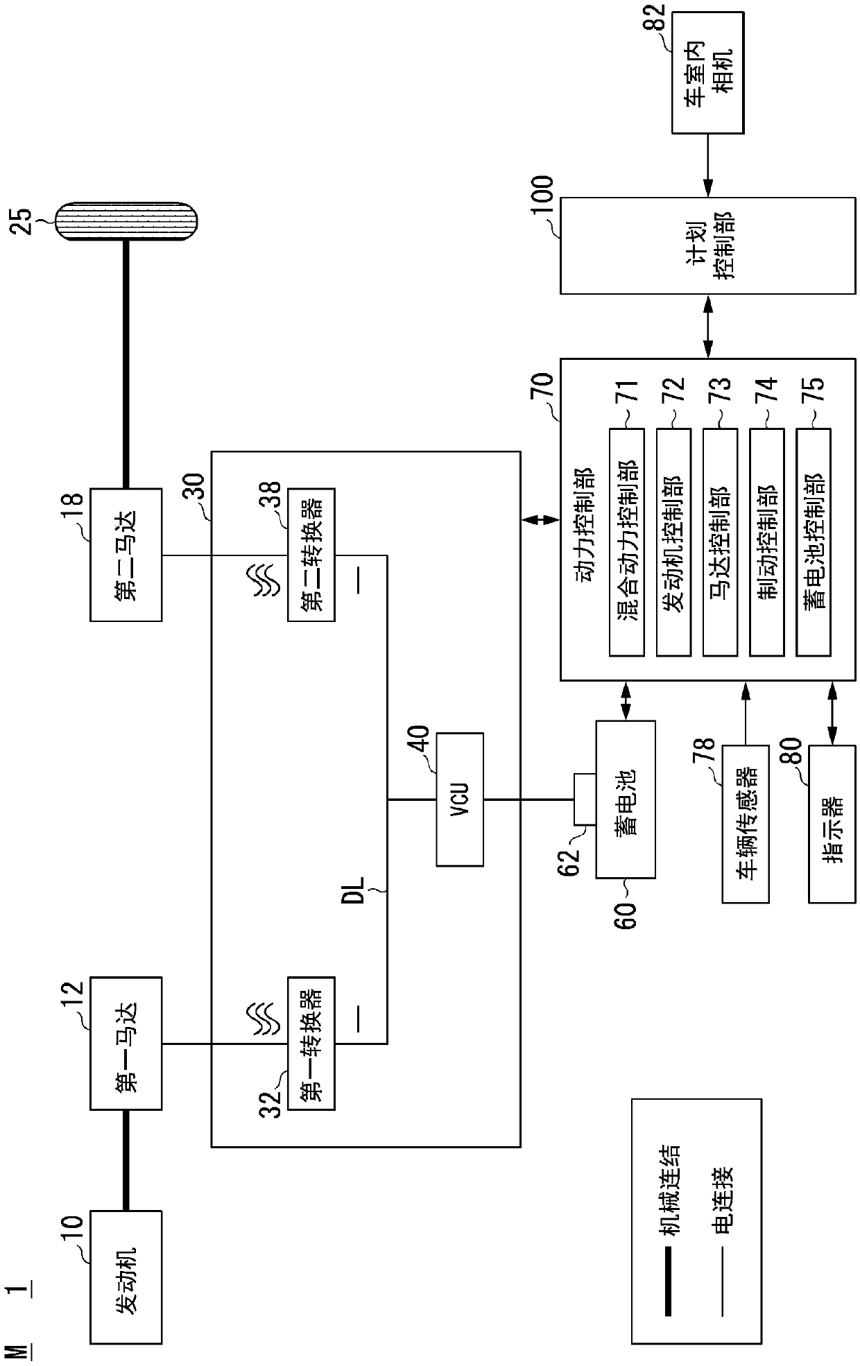
[0042] figure 1 It is a figure which shows an example of the structure of the vehicle (henceforth referred to as own vehicle M) equipped with the vehicle system 1 which includes a vehicle control system. The vehicle on which the vehicle system 1 is mounted is, for example, a two-wheel, three-wheel, or four-wheel vehicle, and its drive source is an internal combustion engine such as a diesel engine or a gasoline engine, an electric motor, or a combination thereof. When an electric motor is provided, the electric motor operates using power generated by a generator connected to the internal combustion engine, or discharged power from a secondary battery or a fuel cell. In the following description, a hybrid vehicle adopting a series system will be described as an example. The series system refers to a system in which the engine and drive wheels are not mechanically connected, the power of the engine is used for power generation by a generator, and the...

no. 2 approach

[0097] Hereinafter, a second embodiment will be described. In the first embodiment, the output level of the power generation section is not mentioned, but in the second embodiment, the output level of the power generation section is mentioned. In the second embodiment, the planning control unit 100 increases the output level of the power generation unit compared to other cases, for example, when the degree of uneasiness is equal to or greater than a predetermined level and the actual SOC is equal to or less than the SOC threshold. Hereinafter, description will focus on matters not described in the first embodiment.

[0098] The control unit 112 passes the later-described Figure 8 processing of the flow chart, to determine the aforementioned Figure 5 The output level of the power generation unit when the power generation unit is operated in step S112 and step S116 in the flow chart of . The level of output refers to the magnitude of the amount of electric power generated b...

no. 3 approach

[0112] Hereinafter, a third embodiment will be described. In the third embodiment, even if the user's degree of uneasiness is higher than a predetermined level, if the actual SOC is not lower than the target SOC by a predetermined power amount or more, the planning control unit does not operate the power generation unit, and outputs an output indicating The actual SOC is information within the planned range. Hereinafter, the description will focus on differences from the first embodiment.

[0113] Figure 11 It is a figure which shows an example of the functional structure of the vehicle system 1A centering on the planning control part 100A of 3rd Embodiment. The vehicle system 1A includes, for example, a display unit 84 and a speaker 86 in addition to the functional configuration of the vehicle system 1 according to the first embodiment. The vehicle system 1A includes a planning control unit 100A instead of the planning control unit 100 of the vehicle system 1 . exist F...


PUM


Abstract

The invention relates to a vehicle control system, a vehicle control method and a storage medium. The vehicle control system may include a power generator, a storage battery, a running electric motor,a determiner configured to determine an area toward which a vehicle occupant of the vehicle has a line of vision directed; a deriver configured to derive an index based on a frequency at which the vehicle occupant has the line of vision directed toward a specific area on the basis of a determination result; and a controller configured to operate the power generator in a case in which an amount ofpower of the storage battery is equal to or smaller than a threshold and operate the power generator regardless of the threshold of the amount of power of the storage battery in a case in which the index derived is equal to or higher than a predetermined degree.

Description

technical field [0001] The invention relates to a vehicle control system, a vehicle control method and a storage medium. Background technique [0002] Conventionally, a vehicle is known that includes a motor that drives drive wheels using electric power stored in a battery that can be charged with electric power from a power generating mechanism and charged with electric power from a charger. In association with this, a vehicle is disclosed which is controlled in such a manner that a target remaining capacity is set based on a remaining battery capacity equivalent to energy required to travel from a current point to a charging point with a power set in advance, and The lower limit remaining of the target remaining capacity is set based on the output power of the battery required for driving the vehicle estimated based on the information related to the actual driving content and the power output characteristic that is the relationship between the remaining capacity of the bat...

Claims


Application Information

Patent Timeline
Patent Type & Authority Applications(China)
IPC IPC(8): B60W20/00
CPCB60W20/00B60K6/46B60W50/10B60W2510/244B60W2540/00B60W20/13B60W40/09B60K35/00B60W2540/225Y02T10/62B60K35/10B60K2360/149B60K35/28B60K2360/169B60K35/60B60W10/06B60W10/08H02J7/14B60Y2200/92B60W2540/22B60W2710/06
Inventor 雨池宽
Owner HONDA MOTOR CO LTD
Why Eureka
Try Eureka