Air guide plate bracket, air guide door and air conditioner
An air deflector and shaft hole technology, which is applied in the field of air conditioners, can solve the problems such as the air deflector being difficult to disassemble, and achieve the effects of improving aesthetics, improving safety and facilitating disassembly.
- Summary
- Abstract
- Description
- Claims
- Application Information
AI Technical Summary
Problems solved by technology
Method used
Image
Examples
Embodiment 1
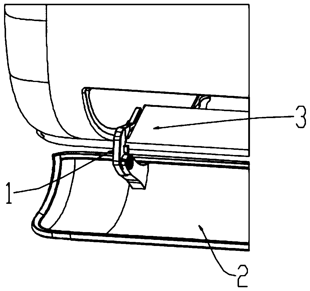
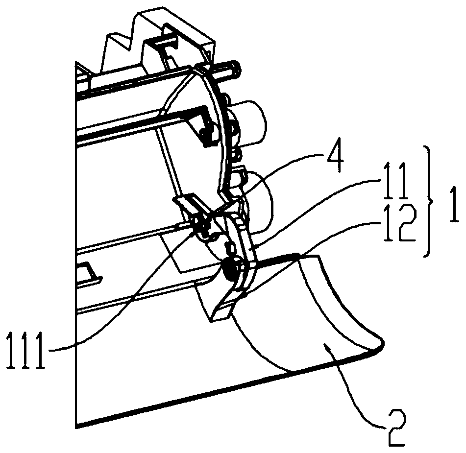
[0045] This embodiment provides a wind deflector bracket, combined with figure 1 and figure 2 As shown, it includes a bracket body 1, the bracket body 1 is used to connect the wind deflector 2 and the motor shaft 4, the motor shaft 4 is connected to the motor, the motor is installed on the base, and the bracket body 1 further drives the wind deflector 2 to rotate when the motor rotates , to realize the opening and closing of the wind deflector 2, in this embodiment, the bracket body 1 includes a first bracket 11 and a second bracket 12, the first bracket 11 is provided with a first mounting part, and the second bracket 12 is provided with There is a second installation part, and the detachable connection between the first installation part and the second installation part realizes the detachable connection between the first bracket 11 and the second bracket 12. When cleaning the wind deflector, you only need to disassemble the second One installation part and the second inst...
Embodiment 2
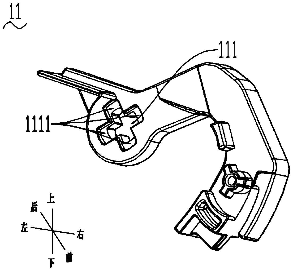
[0047] On the basis of the above-mentioned embodiments, this embodiment combines Figure 1-Figure 4As shown, the first bracket 11 is detachably connected to the motor shaft 4. Specifically, this embodiment provides a clamping method. The first bracket 11 is provided with a first shaft hole 111, and the first shaft hole 111 is cross-shaped. Through hole, the first shaft hole 111 is provided with a first block 1111. There are four first block 1111, which are respectively arranged at the four top ends of the cross-shaped through hole. The motor shaft 4 is provided with an insert block 41 and a buckle 42. The insert 41 is in the shape of a long plate, and there are two buckles 42. The two buckles 42 are mirrored and distributed on both sides of the insert 41. The insert 41 and the two buckles 42 together form a similar cross-shaped structure. , the insert block 41 and the buckle 42 are inserted into the first shaft hole 111, and the two buckles 42 are respectively snapped onto the...
Embodiment 3
[0050] On the basis of the above-mentioned embodiments, this embodiment combines Figure 4-Figure 7 As shown, a specific connection method to realize the functions of the first installation part and the second installation part is provided:
[0051] The first mounting part includes a connecting shaft 112, and the second mounting part includes a second shaft hole 121, or the first mounting part includes a second shaft hole 121, and the second mounting part includes a connecting shaft 112, that is, the connecting shaft and the second shaft hole 121 The positions can be reversed. In this embodiment, the first installation part includes the connecting shaft 112 and the second installation part includes the second shaft hole 121 as an example.
[0052] The connecting shaft 112 can be inserted into the second shaft hole 121, and can rotate relatively around the axis of the connecting shaft 112. The connecting shaft 112 can be inserted into the second shaft hole 121 to rotate, and wh...
PUM
 Abstract
Description
Claims
Application Information
 - R&D
- Intellectual Property
- Life Sciences
- Materials
- Tech Scout
- Unparalleled Data Quality
- Higher Quality Content
- 60% Fewer Hallucinations
Browse by: Latest US Patents, China's latest patents, Technical Efficacy Thesaurus, Application Domain, Technology Topic, Popular Technical Reports.
© 2025 PatSnap. All rights reserved.Legal|Privacy policy|Modern Slavery Act Transparency Statement|Sitemap|About US| Contact US: help@patsnap.com


