Smart flood-control monitoring device for hydraulic engineering

A technology for monitoring devices and water conservancy projects, applied in the direction of measuring devices, towers, building types, etc., can solve problems such as large errors, equipment damage, time-consuming and labor-intensive problems

Active Publication Date: 2019-06-14
韩国
View PDF8 Cites 6 Cited by
  • Summary
  • Abstract
  • Description
  • Claims
  • Application Information

AI Technical Summary

Problems solved by technology

[0002] The measurement of flow velocity is an important part of flood monitoring indicators. At present, most of the flow velocity is measured by manually sinking the flow meter into the water at regular intervals. This method is not only time-consuming and laborious, but the monitored flow velocity is only an instantaneous flow velocity, which cannot objectively reflect the flow of the river. Real-time water situation
When floods occur in the river, manual measurement has great potential safety hazards, and the monitoring results cannot reflect the river flow in a timely and accurate manner, which further reduces the accuracy and efficiency of hydrological forecasting
[0003] Judging whether there is a flood requires multiple complex data, such as the flow rate of water, whether the river bed is piled up, and changes in the air environment, etc., so it needs comprehensive monitoring functions and high-precision instruments. The equipment on the market basically relies on sensors. Remote detection, not only has a large error, but also cannot fully detect the data of the monitoring points
Traditional equipment cannot protect itself when encountering extreme environments, resulting in equipment damage

Method used


Image

  • Smart flood-control monitoring device for hydraulic engineering
  • Smart flood-control monitoring device for hydraulic engineering
  • Smart flood-control monitoring device for hydraulic engineering

Examples


Embodiment Construction

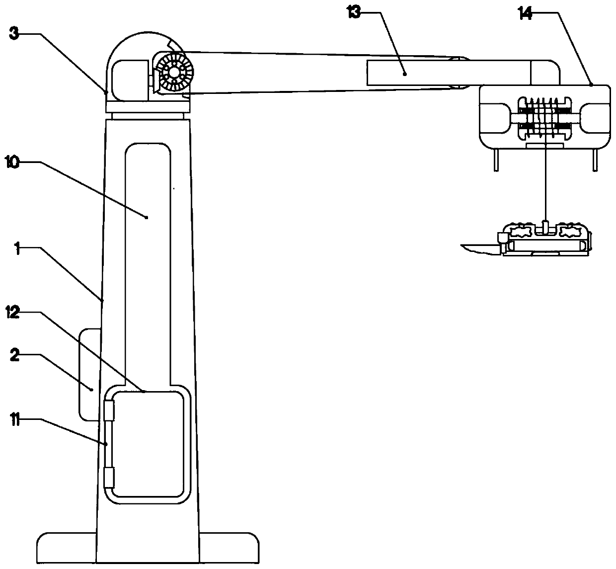
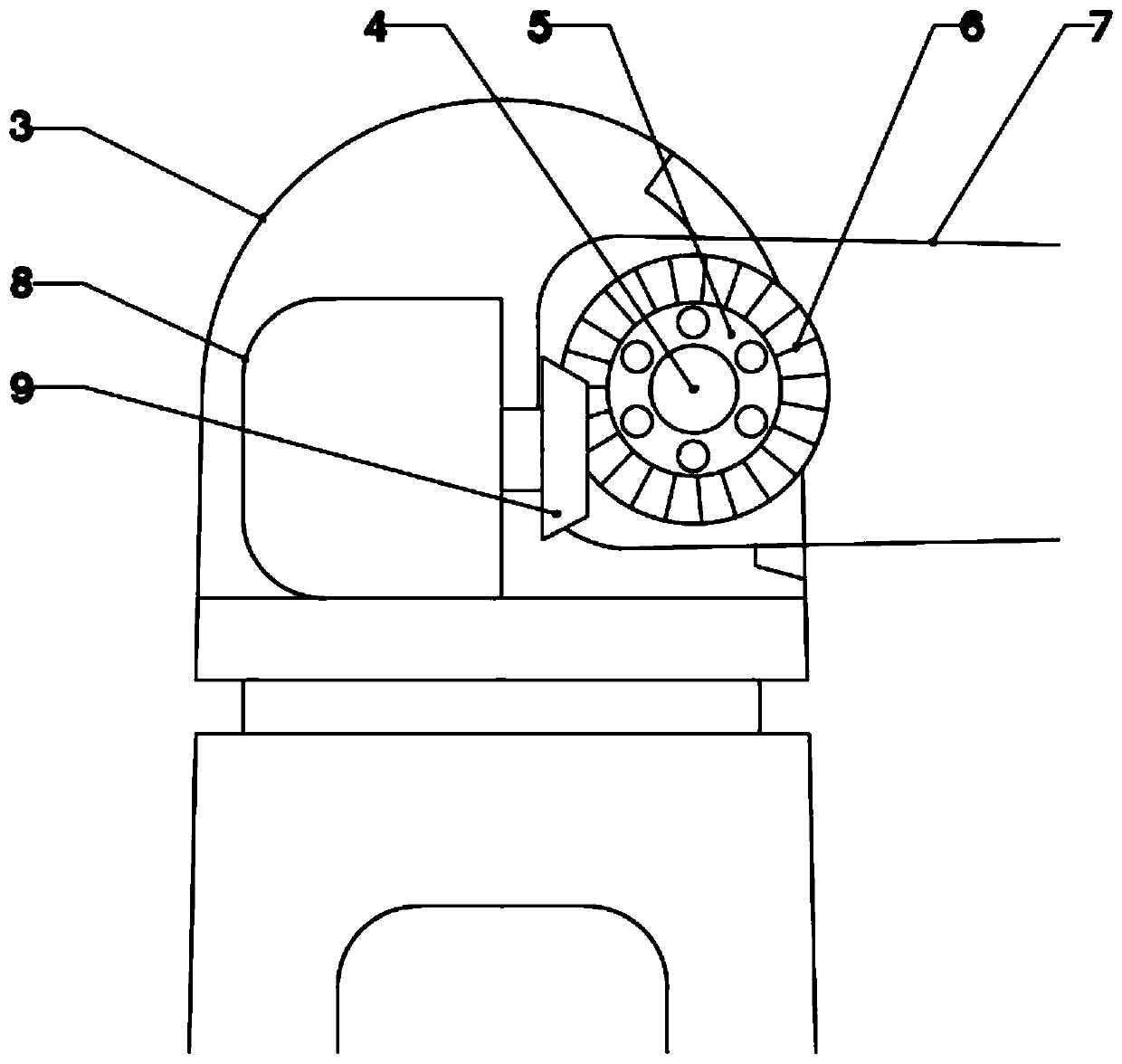
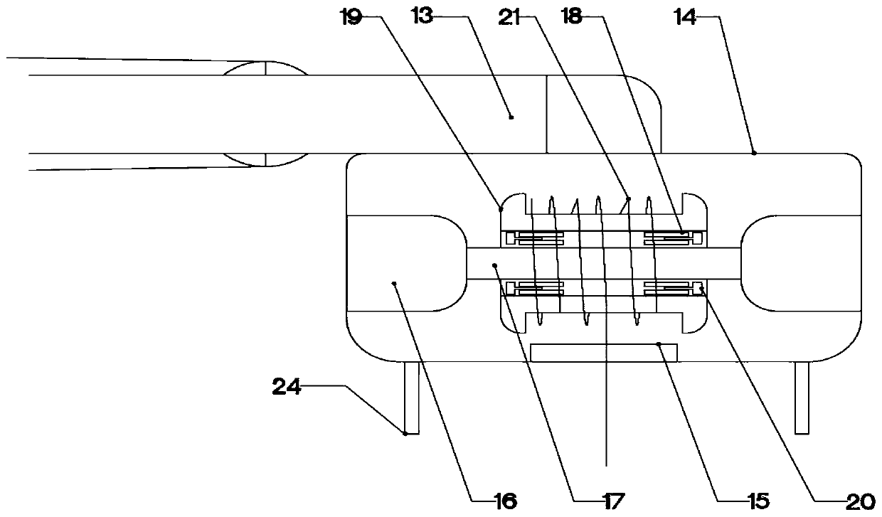
[0019] The present invention is specifically described below in conjunction with accompanying drawing, as Figure 1-4 shown.

[0020] In this embodiment, the data of the water level can be monitored in real time through the function of the water surface height monitoring device, so as to achieve the purpose of accurately monitoring the water level. Through the function of the river silt detection device, the data of the riverbed in different places can be detected, so as to determine whether accumulation occurs. By maintaining the function of the shrinking device, the equipment can be properly protected, thereby improving the service life of the equipment.

[0021] In the first step, the shrinkage groove 10 can accommodate the auxiliary support rod 7, and the rectangular groove 11 can accommodate the water level monitoring device and the river silt detection device. When the environment is extreme or maintenance is required, the controller 2 controls the rotating motor One 8...


PUM


Abstract

The invention discloses a smart flood-control monitoring device for hydraulic engineering. The smart flood-control monitoring device comprises a main support rod, a water surface elevation monitoringdevice, a riverway sludge detection device, and a repair retraction device, wherein the water surface elevation monitoring device is arranged on one side of the main support rod; a lower end of the main support rod is fixedly connected with one side of a riverway; the riverway sludge detection device is arranged below the height monitoring device; the repair retraction device is arranged on one side of the main support rod; the water surface elevation monitoring device drives a spring through a motor, and the spring drives a rope, so that the aim of monitoring the water level is fulfilled by monitoring the length of the rope; the riverway sludge detection device enables the monitoring device to float under the impulsive force of water current, and the changes of a riverbed at different positions are sensed through a sensor; a side surface of the main support rod is provided with a controller; and the controller is fixedly connected with the main support rod. The smart flood-control monitoring device has the beneficial effects of simple structure and high practicability.

Description

technical field [0001] The invention relates to the related field of flood control monitoring devices, in particular to an intelligent flood control monitoring device for water conservancy projects. Background technique [0002] The measurement of flow velocity is an important part of flood monitoring indicators. At present, most of the flow velocity is measured by manually sinking the flow meter into the water at regular intervals. This method is not only time-consuming and laborious, but the monitored flow velocity is only an instantaneous flow velocity, which cannot objectively reflect the flow of the river. Real-time water situation. When floods occur in the river, manual measurement has great potential safety hazards, and the monitoring results cannot reflect the river flow in a timely and accurate manner, which further reduces the accuracy and efficiency of hydrological forecasting. [0003] Judging whether there is a flood requires multiple complex data, such as the ...

Claims


Application Information

Patent Timeline
Patent Type & Authority Applications(China)
IPC IPC(8): G01D21/02E04H12/18
Inventor 施桂英
Owner 韩国
Why Eureka
Try Eureka