
Environment-friendly simple electronic cigarette atomizer

An electronic cigarette atomizer and a simple technology, applied in the field of electronic cigarettes, can solve the problems of easy carbonization of the cotton layer on the surface of the heating net, reducing the user experience, affecting the effect, etc., so as to reduce manpower, improve user experience, and avoid pollution and waste. Effect

Pending Publication Date: 2019-06-18
东莞市轩策五金制品有限公司
View PDF0 Cites 1 Cited by
  • Summary
  • Abstract
  • Description
  • Claims
  • Application Information

AI Technical Summary

Problems solved by technology

At present, electronic vape atomizers on the market generally use the inner wall of the atomizing core to atomize, which is not easy to dissipate heat, and the cotton layer on the surface of the heating net is easy to carbonize, resulting in the need to frequently replace the entire atomizing core, resulting in great waste, and it needs to be wrapped and pressed during assembly. Multi-layer oil cotton has a very complicated structure and requires a lot of manpower. The pressing method or tightness of each person directly affects the effect
At present, the biggest defect of e-cigarettes is that the e-liquid flows from high liquid level to low liquid level due to gravity, seeps through the inner wall of the oil-absorbing layer, and directly flows out through the air inlet, which not only causes waste and pollutes the environment, but also reduces the user's use. sense of experience

Method used


Image

  • Environment-friendly simple electronic cigarette atomizer
  • Environment-friendly simple electronic cigarette atomizer
  • Environment-friendly simple electronic cigarette atomizer

Examples


Embodiment Construction

[0026] The present invention will be described in further detail below in conjunction with the accompanying drawings.

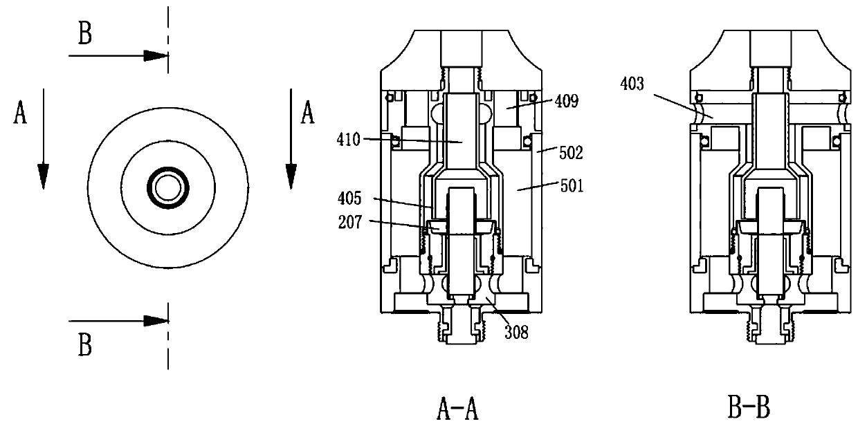
[0027] Combined with the accompanying drawings, from figure 1 It can be seen that the atomizer includes a heating element 100 and an atomizing core assembly 200 located in the electronic cigarette atomizer for heating and atomizing liquid; the atomizing core assembly 200 is screwed into the atomizing seat assembly 300 The middle cavity of the atomizing core assembly 200 is provided with a lower oil-absorbing core 205, and the lower end opening communicates with the oil inlet cavity 308 in the middle of the atomizing seat assembly 300; Tighten it to form oil storage bin 501, air intake channel 403, and air outlet channel 410; the lower edge of the partition cover 405 is arranged below the heating net 101, and the top air intake channel is changed to the lower air intake.

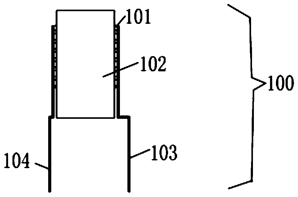
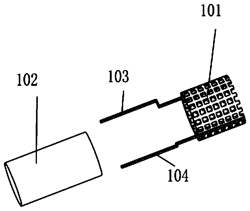
[0028] combine figure 1 , see figure 2 , image 3 , in an embodiment, the heating n...


PUM


Abstract

The invention discloses an environment-friendly simple electronic cigarette atomizer which comprises a heating component, an atomizing core component, an atomizing seat component and a top seat component. Parallel central lines of the outer wall of a heat generating net are welded with a positive electrode pin and a negative electrode pin, a core, the lower-end surface of a silica gel pipe, the lower-end outer surface of a position electrode pipe, the middle inner wall of an atomizing seat, a silica gel sleeve and a positive electrode surround to form an oil incoming cavity, an inwards-concaveface, the upper end face of the silica gel pipe, the outer surface of an upper oil absorbing core and the inner surface of a connection cover surround to form a seeping oil collection cavity, and thelower-end outer surface of a top seat, the inner wall of a glass pipe, the inner wall of a base and the upper-end outer surface of the atomizing seat surround to form an oil storage bin. The heatingcomponent generates heat on the outer surface for atomization, so that convenience is brought to heat radiation, and the surface is less prone to carbonization; when the surface of a heating net carbonizes, replacement of the atomizing core component is not needed, and only the heating component needs to be replaced, so that waste is reduced, and using cost of users is lowered; seeping tobacco taris recycled, so that pollution and waste caused by direction emission are avoided, and user experience is improved.

Description

technical field [0001] The invention relates to the technical field of electronic cigarettes, in particular to an environmentally friendly and simple electronic cigarette vaporizer. Background technique [0002] E-cigarettes are electronic products that mimic cigarettes, with the same smoke, taste and feel as cigarettes. It is a product that allows users to smoke after turning e-liquid into steam by means of atomization and other means. At present, electronic vape atomizers on the market generally use the inner wall of the atomizing core to atomize, which is not easy to dissipate heat, and the cotton layer on the surface of the heating net is easy to carbonize, resulting in the need to frequently replace the entire atomizing core, resulting in great waste, and it needs to be wrapped and pressed during assembly. Multi-layer oil cotton has a very complicated structure, which requires a lot of manpower, and each person's pressing method or tightness directly affects the effect...

Claims


Application Information

Patent Timeline
IPC IPC(8): A24F47/00
Inventor 孟红霞
Owner 东莞市轩策五金制品有限公司
Learn More