Production method of porous mesh steel strip reinforced composite tube

A technology for enhancing compounding and production methods, applied in the direction of tubular articles, other household appliances, household appliances, etc., can solve the problems of high cost, low efficiency, affecting the surface quality of the composite pipe, etc., and achieve the effect of large traction force and reliable traction force.

Active Publication Date: 2019-06-18
ZHANGJIAGANG XIEXIN MACHINERY
View PDF3 Cites 0 Cited by
  • Summary
  • Abstract
  • Description
  • Claims
  • Application Information

AI Technical Summary

Problems solved by technology

[0003] 1. The surface of the composite pipe formed by the current composite molding device is not smooth, and there will be rotational friction between the rotating composite pipe and the mold, thereby forming spiral traces on the surface of the composite pipe, which are extremely large Affect the appearance quality of the composite pipe
[0004] 2. After the rotating steel belt pipe and plastic are compounded in the compound molding mold, they cannot be pulled by the tractor. The current tractor can only pull the non-rotating steel belt reinforced composite pipe, and the rotating steel belt reinforced composite pipe will not be drawn by the traction machine. The friction between the machines will seriously affect the surface quality of the composite pipe
Obviously this method is inefficient and more expensive

Method used


Image

  • Production method of porous mesh steel strip reinforced composite tube
  • Production method of porous mesh steel strip reinforced composite tube
  • Production method of porous mesh steel strip reinforced composite tube

Examples


Embodiment Construction

[0033] The present invention will be described in further detail below through specific examples.

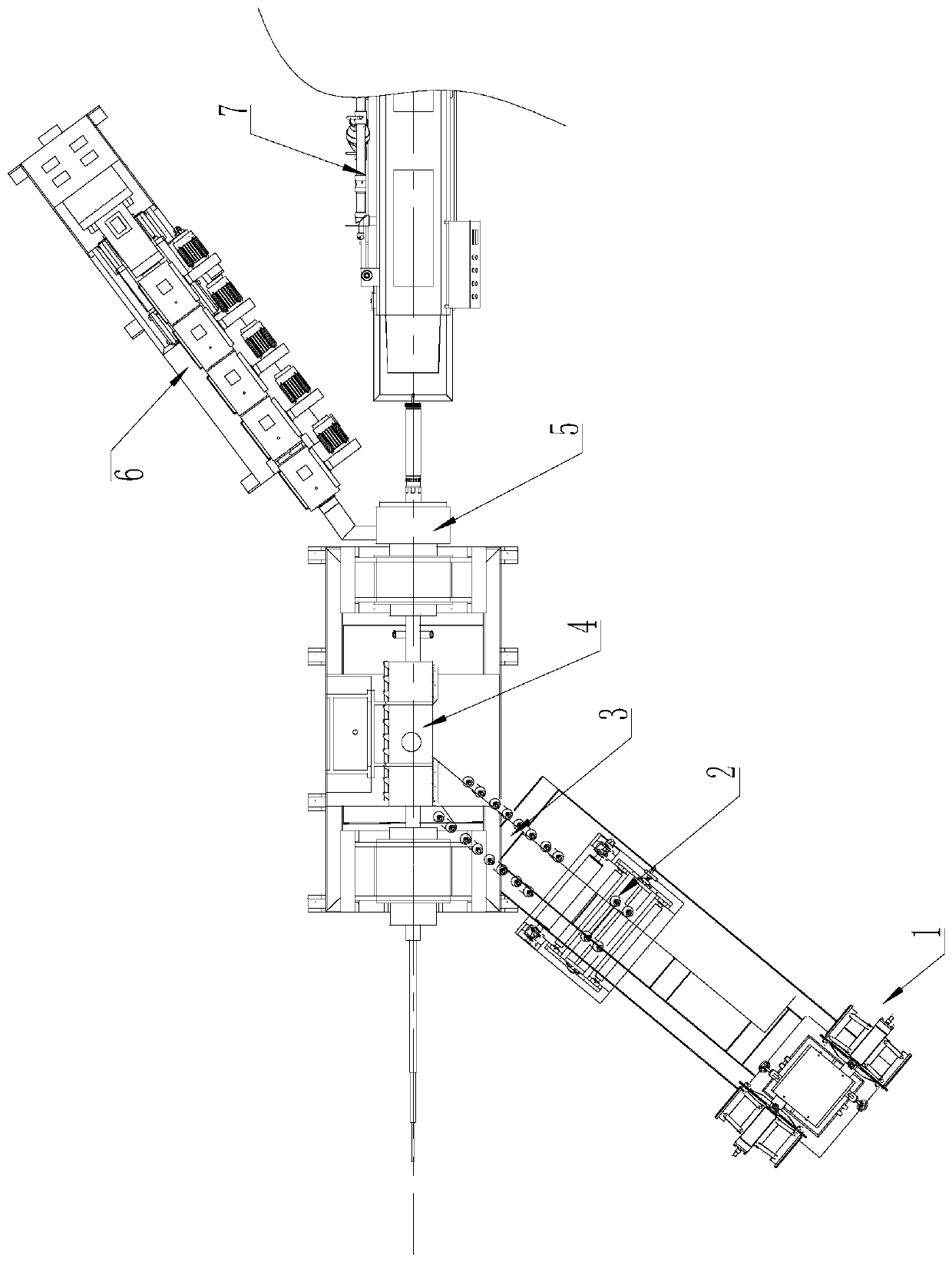
[0034] A method for producing a perforated steel strip reinforced composite pipe, comprising the following steps:

[0035] S1. Continuously unwind the perforated steel strip from the unwinder;

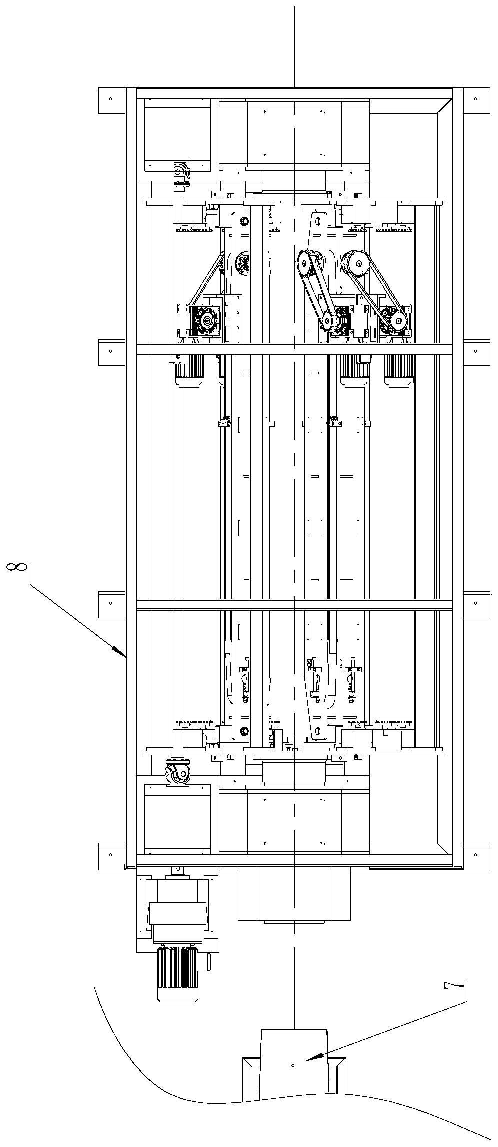
[0036] S2. The unrolled perforated steel strip is obliquely wound on the welding support cylinder of the rotary welding forming device and welded into a steel strip welded pipe;

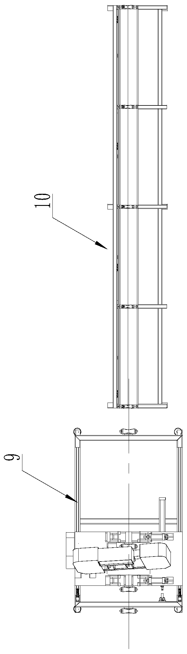
[0037] S3. The steel strip welded pipe rotates through the rotary composite molding die, and the plastic fluid extruded by the extruder enters the rotary composite molding mold to form an inner plastic layer and an outer plastic layer wrapping the steel strip welded pipe. The front end of the rotary composite molding mold is equipped with The steel strip welded pipe rotates in the same direction and at the same speed as the outer sizing die, and the compounded pipe passes through the inner hole of the outer si...


PUM


Abstract

The invention discloses a production method of a porous mesh steel strip reinforced composite tube. The production method comprises the following steps: S1, a hole mesh steel strip is unreeled from aunreeling machine; S2, the rolled perforated mesh steel strip obliquely winds a welding support barrel to be welded to form a steel strip welded tube; S3, the steel strip welded tube is rotated and penetrates through a rotary composite forming die, plastic fluid extruded by an extruder enters the rotary composite forming die to form an inner plastic layer and an outer plastic layer which wrap thewelded tube of the steel strip, the front end of the rotary composite forming die is provided with an outer sizing die which is in the same direction as the steel strip welded tube to rotate at the same speed, and the composite tube is subjected to outer sizing through the inner hole of the outer sizing die; S4, the composite tube is conveyed into a cooling box for cooling; S5, the composite tubeis synchronously and rotationally dragged by a rotary traction device; S6, the composite tube is cut through an online synchronous cutting machine; and S7, the cut composite tube is folded and stored.The production method can produce the porous mesh steel strip reinforced composite tube with high surface quality on a continuous production line.

Description

technical field [0001] The invention relates to a production method of a perforated mesh steel strip reinforced composite pipe, and belongs to the technical field of composite production of plastic and metal pipes. Background technique [0002] The perforated steel strip reinforced composite pipe is formed by combining the plastic pipe and the steel strip welded pipe wound by the perforated steel strip. However, in the current forming process of the steel strip composite pipe, the steel strip passes through the steel coil machine After unwinding, argon arc welding is carried out on the rotary welding machine, and the steel strip is obliquely wrapped on the welding support cylinder to be welded into a tubular structure. However, because the steel strip welded pipe formed by welding is rotating, and the rotating pipe cannot be directly compounded in terms of the current process, the main reasons are two points: [0003] 1. The surface of the composite pipe formed by the curre...

Claims


Application Information

Patent Timeline
IPC IPC(8): B29D23/00
Inventor 陆宇航孙德金
Owner ZHANGJIAGANG XIEXIN MACHINERY
Why Eureka
Try Eureka