
Connecting rod with bearing bush mounted easily

An easy-to-install, connecting rod technology, applied in the directions of connecting rod, connecting rod bearing, shaft and bearing, etc., can solve the problems of complete machine damage, out-of-round deformation of connecting rod large end, bending deformation of rod body, etc., to ensure normal use and manufacturing. Convenience and longevity

Inactive Publication Date: 2019-06-18
扬州市邗江华兴机械有限公司
View PDF0 Cites 0 Cited by
  • Summary
  • Abstract
  • Description
  • Claims
  • Application Information

AI Technical Summary

Problems solved by technology

Insufficient fatigue strength will often cause the connecting rod body or connecting rod bolts to break, and then cause a major accident of complete machine damage
If the rigidity is insufficient, it will cause bending deformation of the rod body and out-of-round deformation of the big end of the connecting rod, resulting in eccentric wear of the piston, cylinder, bearing and crank pin, etc.
The existing connecting rod bearing bush is directly connected between the big end of the connecting rod and the closing cover. During the installation process, the upper and lower connecting rod bearing bushes are basically positioned, but there is no positioning measure between the upper and lower connecting rod bearing bushes and the connecting rod big end. During the process, misalignment is prone to occur, thus affecting normal use

Method used


Image

  • Connecting rod with bearing bush mounted easily
  • Connecting rod with bearing bush mounted easily

Examples


Embodiment Construction

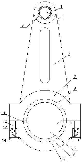
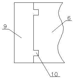
[0014] A connecting rod for easy installation of bearing bushes, comprising a small connecting rod head 1, a large connecting rod head 2, and a connecting rod body 3 for connecting the small connecting rod head 1 and the large connecting rod head 2, the small connecting rod head 1 is provided with Connecting small hole 4, the inner bushing 5 is installed in the connecting small hole 4, the lower end of the connecting rod big head 2 is provided with a gap, the closing cover 6 is installed on the gap, and the closing cover 6 and the gap form a large connecting hole 7, connecting the large The upper connecting rod bearing bush 8 and the lower connecting rod bearing bush 9 are installed in the hole 7, and the outer surfaces of the upper connecting rod bearing bush 8 and the lower connecting rod bearing bush 9 are respectively provided with arc-shaped bosses 10, and the inner wall of the closing cover 6 and the inner wall of the gap are respectively provided with There is an arc-sha...


PUM


Abstract

The invention relates to a connecting rod with bearing bushes mounted easily. The connecting rod comprises a small connecting rod end, a large connecting rod end, and a connecting rod body enabling the small connecting rod end to be connected with the large connecting rod end. A small connecting hole is formed in the small connecting rod end. A neck bush is mounted in the small connecting hole. Anotch is formed in the lower end of the large connecting rod end. A closure cover is mounted on the notch. A large connecting hole is defined by the closure cover and the notch. The upper connecting rod bush and the lower connecting rod bush are mounted in the large connecting hole. Arc-shaped bosses are arranged on the outer surfaces of the upper connecting rod bush and the lower connecting rod bush correspondingly. Arc-shaped positioning grooves matched with the arc-shaped bosses are formed in the inner wall of the closure cover and the inner wall of the notch correspondingly. The two sidesof the closure cover are connected with the large connecting rod end through bolts correspondingly. Spring sleeving the bolts are arranged between the lower end surface of the closure cover and the bolts correspondingly. The connecting rod is simple in structure, the upper and lower connecting rod bushes, the large connecting rod end and the closure cover are combined conveniently and fast, it canbe effectively guaranteed that the connecting rod is normally used, and the service life is prolonged.

Description

technical field [0001] The invention relates to a connecting rod, in particular to a connecting rod which is easy to install a bearing bush. Background technique [0002] The connecting rod group is composed of connecting rod body, connecting rod big head cover, connecting rod small end bushing, connecting rod big end bearing bush and connecting rod bolts (or screws). The connecting rod group is subjected to the gas force from the piston pin, its own swing and the reciprocating inertial force of the piston group. The magnitude and direction of these forces change periodically. Therefore, the connecting rod is subjected to alternating loads such as compression and tension. The connecting rod must have sufficient fatigue strength and structural rigidity. Insufficient fatigue strength will often cause the connecting rod body or connecting rod bolts to break, and then cause a major accident of complete machine damage. If the rigidity is insufficient, it will cause bending def...

Claims


Application Information

Patent Timeline
Patent Type & Authority Applications(China)
IPC IPC(8): F16C7/02F16C9/04
Inventor 高国祥
Owner 扬州市邗江华兴机械有限公司
Learn More