Surface formwork system for building with frame structure and application thereof

A frame structure and building surface technology, which is applied in the direction of architecture, building structure, formwork/formwork components, etc., can solve the problems of high deformation stiffness, limited fiber reinforcement effect, and increased cost, and achieve enhanced longitudinal bending and torsion resistance Effects of rigidity, cost reduction and difficulty of assembly and disassembly, and service life extension

Inactive Publication Date: 2012-04-11
QINGDAO TECHNOLOGICAL UNIVERSITY
View PDF13 Cites 7 Cited by
  • Summary
  • Abstract
  • Description
  • Claims
  • Application Information

AI Technical Summary

Problems solved by technology

However, the effect of simply using fiber reinforcement is limited, and the cost is greatly increased; on the other hand, it can also be achieved by changing the structural form of the plastic material or the wood-plastic composite panel itself and increasing the stiffness, as mentioned in the patent 200520035704.9 by increasing the solid Or the hollow rib plate changes the cross-sectional shape of the wood-plastic composite material board, and then obtains a higher deformation stiffness of the wood-plastic composite material board
However, this technical solution is difficult to disassemble due to the use of foaming agent and non-stick glue sealing when the veneer surface templates are spliced ​​together, and it is not easy to clean up, which affects the multiple recycling of wood-plastic composite boards, making it not very practical ; In addition, in the patent 201010557314.3, it is also proposed to set the joint to improve the strength of the joint and prevent the method of leakage
However, this patent only improves the strength of the joint by setting reinforcement bars and steel bars, but does not improve the overall strength of the formwork, and the design of the joint is too complicated, easy to damage, and high in cost, making it difficult to achieve large-scale application
[0004] To sum up, the existing application technology of using plastic materials or wood-plastic composite materials to make veneer face forms and then assemble them into combined face forms generally has defects such as low practicability, many connecting components, low assembly efficiency, and poor economy. , has directly affected the further popularization and application of such products and technologies in the field of construction

Method used


Image

  • Surface formwork system for building with frame structure and application thereof
  • Surface formwork system for building with frame structure and application thereof
  • Surface formwork system for building with frame structure and application thereof

Examples


Embodiment 1

[0040] Such as Figure 4 and Figure 5 The building face formwork system with frame structure of the present invention is shown, which is composed of face formwork units and frame structures.

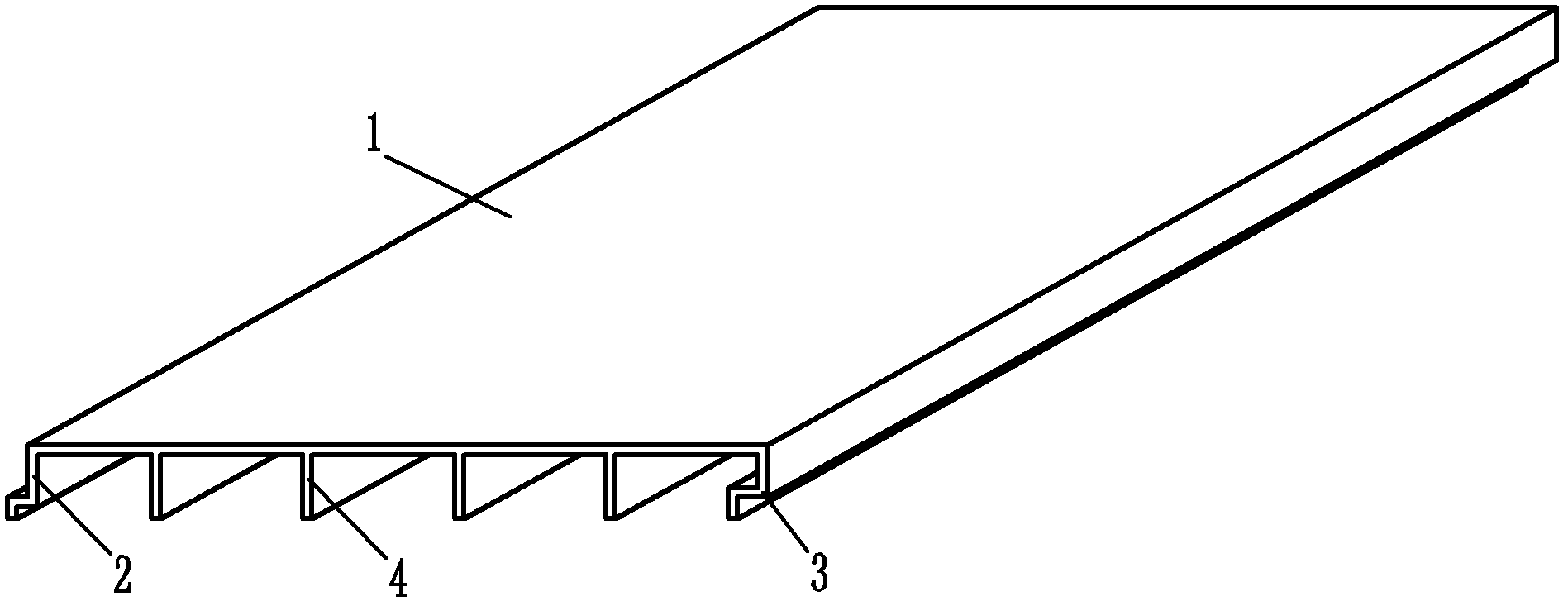
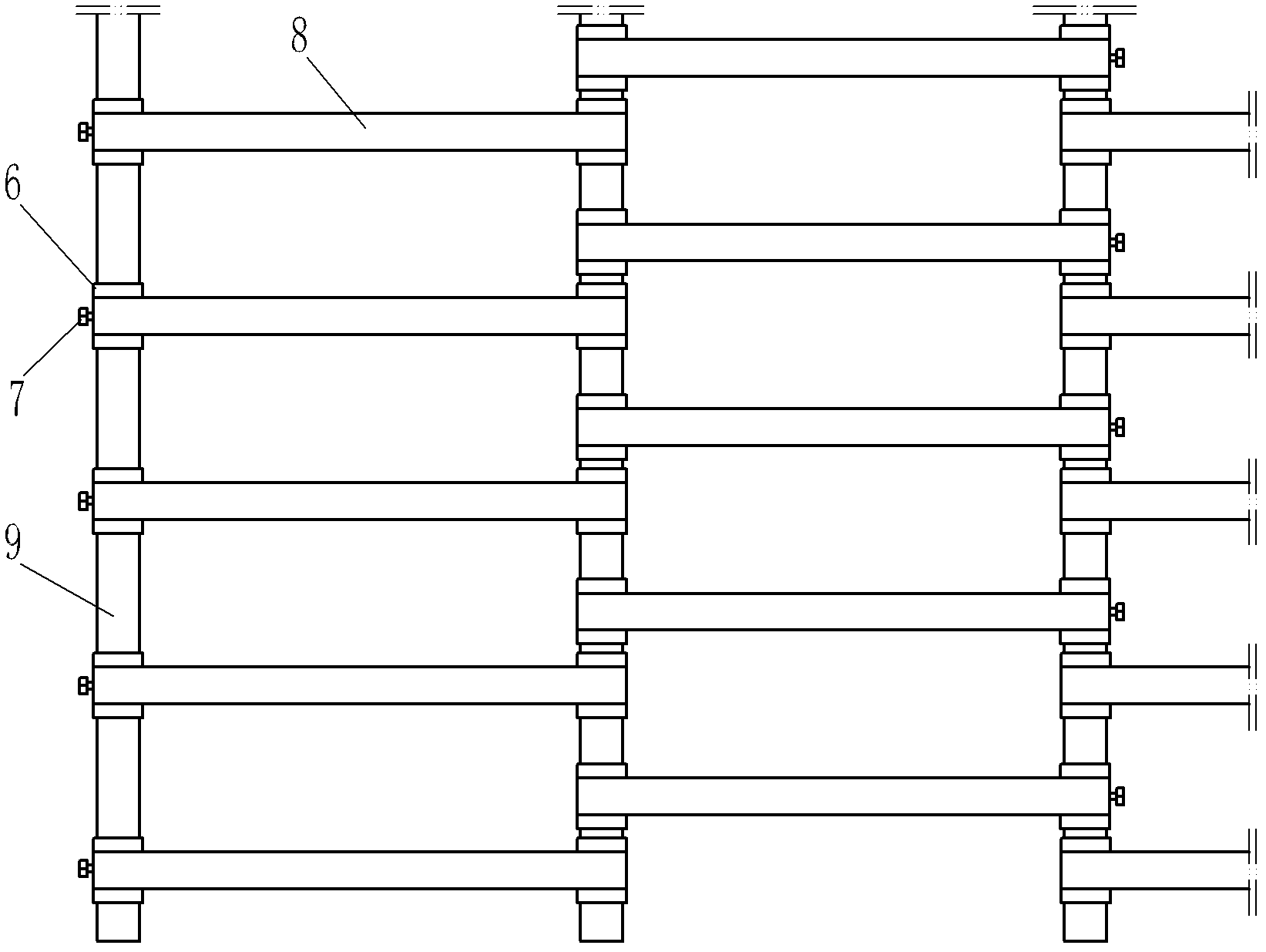
[0041] The surface formwork unit 1 is made of wood-plastic composite material. The longitudinal sides of the formwork unit 1 are respectively provided with connecting ribs 2 and 3, wherein the connecting rib 2 on one side is provided with protrusions, and the connecting rib 3 on the other side is provided with corresponding Grooves are set, and the wood-plastic surface formwork unit 1 is also provided with reinforcing ribs 4 along the longitudinal direction of its plate body. The reinforcement ribs 4 and the connecting ribs 2 and 3 are located on the same side of the wood-plastic surface formwork unit 1, specifically as figure 1 shown. frame structure such as image 3 shown, including figure 2 The longitudinal link 5 and the transverse link 9 are shown, and the longitudinal link 5 ...

Embodiment 2

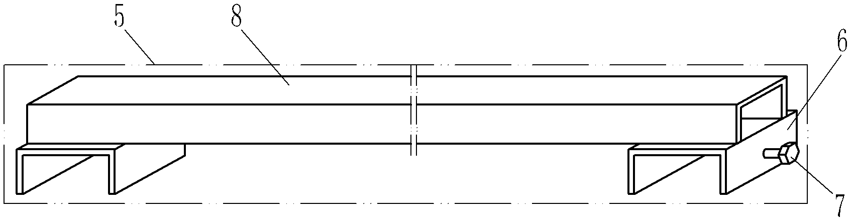
[0048] Such as Figure 8 The difference between the building surface formwork system with frame structure of the present invention shown in Embodiment 1 is that the longitudinal link structure in the frame structure can be varied, such as Figure 6 As shown, the longitudinal connecting rod includes a supporting connecting rod 8 made of steel pipe and a connecting piece 6 made of channel steel, and fastening screws 7 are arranged on the outer end faces of the connecting piece 6 on both sides. Correspondingly, yes Figure 7 As shown, in the surface formwork unit 1 used, the size of the gap between the reinforcing ribs 4 is adapted to the size of the supporting link 8 .

[0049] Transverse connecting rod 9 made of channel steel and Figure 6 The frame structure formed by the longitudinal links shown, with Figure 6 When the surface formwork unit shown constructs the building surface formwork system with frame structure of the present invention, the process can refer to the pro...

Embodiment 3

[0052] Such as Figure 9 The difference between the building surface formwork system with a frame structure of the present invention and the first embodiment is that the frame structure also includes columns 11 . When building a frame structure, such as Figure 10 As shown, the threaded hole on the connecting block 12 fixedly welded inside the transverse connecting rod 9 cooperates with the screw rod 13 fixedly arranged on the top of the column 11 to realize the fixed connection between the column 11 and the transverse connecting rod 9 . The longitudinal link 5 is still erected on the transverse link 9 by means of the connectors provided at both ends.

[0053] Due to the addition of uprights 11, the building surface formwork system with frame structure of the present invention described in this example can be used to construct building formwork systems of various heights in addition to the advantages described in Embodiment 1. The applicability is stronger.

[0054] Based o...


PUM


Abstract

The invention relates to a building formwork, which comprises surface formwork units and a frame structure, wherein the surface formwork units are paved on the surface of the frame structure; connecting ribs are respectively arranged on two sides along a longitudinal direction of formwork bodies of the surface formwork units; a bulge is arranged on the connecting rib on one side; a slot is correspondingly formed on the connecting rib on the other side; reinforcing ribs are arranged along the longitudinal direction of the formwork bodies; the reinforcing ribs and the connecting ribs are located on the same sides of the surface formwork units; the frame structure comprises a longitudinal connecting rod and a lateral connecting rod; the longitudinal connecting rod is arranged on the lateral connecting rod; the surface formwork units are arranged on the surface of the longitudinal connecting rod; the longitudinal connecting rod is at least locally embedded between the reinforcing ribs and / or between the reinforcing ribs and the connecting ribs of the surface formwork units; and adjacent surface formwork units are tightly connected to each other by the correspondingly arranged bulge and slot on the connecting ribs and are fastened by a U-shaped buckle. The building formwork has the advantages of less steel usage, high practicability, high splicing efficiency, easiness in operation, economical and environmentally-friendly properties, excellent stability and evenness, capability of effectively preventing slurry leakage, and wide market prospect.

Description

technical field [0001] The invention belongs to the field of building construction tools, and relates to a building template, in particular to a building template system that can be assembled and reused. Background technique [0002] Used in various modern complex projects, such as high-rise buildings, municipal bridges, dams, tunnels and other cast-in-place concrete formwork technology directly affects the quality, cost and appearance of the project, conventional steel formwork, wood (bamboo) plywood, etc. are no longer good meet their various needs. Various industrial plastic materials and wood-plastic composite materials made of waste wood fibers and thermoplastic polymer materials through hot pressing (molding), extrusion or injection have developed rapidly since the end of the last century. The modern building formwork developed by composite materials not only has the surface non-bonding concrete, smooth surface, moisture-proof and moisture-proof, water-resistant and m...

Claims


Application Information

Patent Timeline
Patent Type & Authority Applications(China)
IPC IPC(8): E04G9/08E04G17/02E04G11/08
Inventor 李秋义罗健林秦原高嵩
Owner QINGDAO TECHNOLOGICAL UNIVERSITY
Why Eureka
Try Eureka