Three-speed device with parts convenient to replace and capable of providing high speed ratio

A technology that replaces parts and has a large speed ratio. It is applied to the transmission device, transmission device parts, gear transmission device, etc., which can solve the problems of inconvenient replacement of parts, and achieve the effects of convenient fixed installation, improved use efficiency and convenient use.

Inactive Publication Date: 2019-06-18
西安佳纳环保科技有限公司
0 Cites 0 Cited by

AI-Extracted Technical Summary

Problems solved by technology

[0005] Aiming at the deficiencies of the prior art, the present invention provides a three-speed device with a large speed ratio that is conv...

Method used

And, by the setting of fixing plate 17 and fixing hole 18, reached the effect that device is fixedly installed conveniently, thereby facilitated the user's use, also improved the service efficiency of device with this, thereby also improved The working efficiency of the device is also convenient for the user.
Embodiments of the present invention provide a kind of three-speed device that is convenient to replace parts and can provide a large speed ratio, as shown in Figure 1-3, comprising a housing 1, the front surface of the housing 1 is movably connected with a box through a hinge Door 15, the front surface of box door 15 is fixedly equipped with handle 16, and the bottom of housing 1 is fixedly installed with fixed plate 17, offers fixing hole 18 on the fixed plate 17, the quantity of fixed plate 17 is four, and four fixed The plates 17 are distributed at the four corners of the bottom of the housing 1. The setting of the fixing plates 17 and the fixing holes 18 achieves the effect of conveniently fixing and installing the device, thereby facilitating the use of the user. The top of the housing 1 is sequentially arranged from left to right The transmission rod 2, the first rotating rod 3 and the second rotating rod 4 are interspersed. The top of 20 is fixedly connected to the top of the inner cavity of the housing 1, and the ends of the transmission rod 2, the first rotating rod 3 and the second rotating rod 4 near the housing 1 all pass through the top of the housing 1 and extend to the inside of the housing 1. One end of the rod 2 located inside the housing 1 is rotatably connected to a sleeve 5, the bottom of the sleeve 5 is fixedly connected to the bottom of the inner cavity of the housing 1, the surface of the transmission rod 2 and located inside the housing 1 is interspersed with a gear 6 One end of the rotating rod-3 locat...

Abstract

The invention provides a three-speed device with parts convenient to replace and capable of providing a high speed ratio, and relates to the field of speed changers. The three-speed device with the parts convenient to replace and capable of providing the high speed ratio comprises a shell body, wherein a transmission rod, a rotating rod I, a rotating rod II are sequentially arranged on the top ofthe shell body from left to right in an interpenetrating mode, and the ends, close to the shell body, of the transmission rod, the rotating rod I and the rotating rod II all penetrate through the topof the shell body and extend into the shell body. According to the three-speed device with the parts convenient to replace and capable of providing the high speed ratio, by arranging a clamping rod, asliding plate, a clamping ring, a tube body, nuts, a spring and a rotating disk, the effect of the convenient replacement of the parts of the three-speed device capable of providing the high speed ratio is achieved, and thus the use of users is facilitated, the working efficiency of the three-speed device capable of providing the high speed ratio is further improved, meanwhile, the use efficiencyof the three-speed device capable of providing the high speed ratio is further improved, and the use of the users is further facilitated.

Application Domain

Toothed gearingsGearing details

Technology Topic

Control theory

Image

  • Three-speed device with parts convenient to replace and capable of providing high speed ratio
  • Three-speed device with parts convenient to replace and capable of providing high speed ratio
  • Three-speed device with parts convenient to replace and capable of providing high speed ratio

Examples

  • Experimental program(1)

Example Embodiment

[0022] The technical solutions in the embodiments of the present invention will be clearly and completely described below in conjunction with the accompanying drawings in the embodiments of the present invention. Obviously, the described embodiments are only a part of the embodiments of the present invention, rather than all the embodiments. Based on the embodiments of the present invention, all other embodiments obtained by those of ordinary skill in the art without creative work shall fall within the protection scope of the present invention.
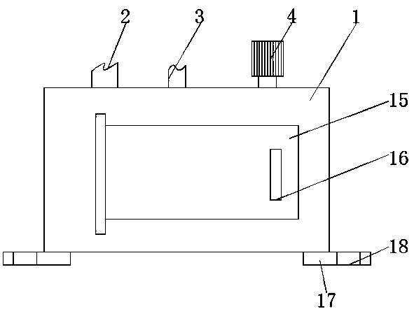
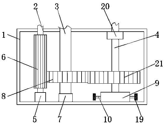
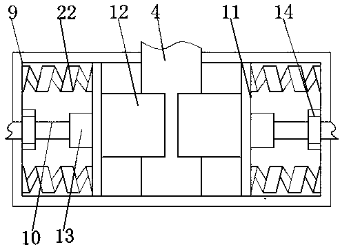
[0023] The embodiment of the present invention provides a three-speed device with a large speed ratio that is convenient to replace parts, such as Figure 1-3 As shown, the housing 1 is included. The front surface of the housing 1 is movably connected with a box door 15 through a hinge. The front surface of the box door 15 is fixedly installed with a handle 16, and the bottom of the housing 1 is fixedly installed with a fixing plate 17. 17 is provided with fixing holes 18, the number of fixing plates 17 is four, and the four fixing plates 17 are distributed at the four corners of the bottom of the casing 1. The fixing plate 17 and fixing holes 18 are arranged to facilitate the fixed installation of the device The effect of this, thereby facilitating the use of the user, the top of the housing 1 is interspersed with a transmission rod 2, a turning rod 3, and a turning rod 4 from left to right. The surface of the turning rod 2 4 is located on the surface of the housing 1. The inner sleeve is equipped with a limit tube 20 that is adapted to the rotating rod two 4. The top of the limit tube 20 is fixedly connected with the top of the inner cavity of the housing 1, and the transmission rod 2, the rotating rod one 3 and the rotating rod two 4 are close to the shell One end of the body 1 penetrates the top of the housing 1 and extends to the inside of the housing 1. The end of the transmission rod 2 located inside the housing 1 is rotatably connected with a sleeve 5, the bottom of the sleeve 5 and the bottom of the inner cavity of the housing 1 Fixed connection, the surface of the transmission rod 2 and the inside of the housing 1 is interspersed with a gear 6; the end of the rotating rod 3 located inside the housing 1 is rotatably connected with a sleeve 7, and the bottom of the sleeve 7 is in the housing 1. The bottom of the cavity is fixedly connected, the surface of the rotating rod 3 and the inside of the housing 1 is interspersed with gear two 8, the gear one 6 and the gear two 8 mesh with each other, and the end of the rotating rod 4 located inside the housing 1 is interspersed with The card box 9, the end of the second rotating rod 4 close to the card box 9 penetrates the top of the card box 9 and extends to the inside of the card box 9. Both sides of the card box 9 are interspersed with a lever 10, and the lever 10 is close to the card box. One end of 9 penetrates one side of the card box 9 and extends to the inside of the card box 9. The surface of the rotating rod 2 4 and the inside of the housing 1 is interspersed with a gear 3 21. The gear 3 21 and the gear 2 8 mesh with each other. A turntable 19 is fixedly installed at one end of the rod 10 outside the cartridge 9. The surface of the turntable 19 is provided with anti-skid protrusions. The arrangement of the turntable 19 achieves the effect of facilitating the rotation of the clamping rod 10.
[0024] The card box 9 is provided with two slide plates 11, the surface of the slide plate 11 is in contact with the inner wall of the card box 9, and the opposite sides of the two slide plates 11 are fixedly installed with a snap ring 12, the snap ring 12 and the rotating rod 4 are located The inner surface of the cartridge 9 is in contact with the bottom of the rotating rod 2 4 is in contact with the bottom of the inner cavity of the cartridge 9, the end of the clamping rod 10 located inside the cartridge 9 is rotatably connected to the pipe body 13, and the end of the pipe body 13 away from the clamping rod 10 Fixedly connected to one side of the sliding plate 11, the surface of the clamping rod 10 and located inside the cartridge 9 is threadedly connected with a nut 14 that matches the clamping rod 10, and one side of the nut 14 is fixed to one side of the inner cavity of the cartridge 9 For connection, a spring 22 is fixedly installed on one side of the sliding plate 11 and located above and below the tube body 13, and the side of the spring 22 away from the sliding plate 11 is fixedly connected to the inner cavity of the card box 9.
[0025] Working principle: When in use, the clamping lever is rotated by the turntable, which facilitates the rotation of the clamping lever 10, and under the action of the nut 14, the sliding plate 11 is moved to facilitate the clamping ring 12 to rotate the lever The second 4 has the effect of loosening, thus facilitating the effect of replacement.
[0026] In summary, this easy-to-replace three-speed device with a large speed ratio can be achieved by setting the lever 10, the sliding plate 11, the snap ring 12, the tube body 13, the nut 14, the spring 22 and the turntable 19 It is convenient to replace the parts of the three-speed device that can provide a large speed ratio, thereby facilitating the user's use, thereby also improving the working efficiency of the three-speed device that can provide a large speed ratio, and also improving the The speed ratio of the three-speed device is efficient, so it is also convenient for users to use.
[0027] Moreover, through the arrangement of the fixing plate 17 and the fixing hole 18, the effect of facilitating the fixed installation of the device is achieved, thereby facilitating the use of the user, thereby also improving the use efficiency of the device, thereby also improving the work of the device Efficiency, which also facilitates the use of users.
[0028] It should be noted that in this article, relational terms such as first and second are only used to distinguish one entity or operation from another entity or operation, and do not necessarily require or imply one of these entities or operations. There is any such actual relationship or order between. Moreover, the terms "include", "include" or any other variants thereof are intended to cover non-exclusive inclusion, so that a process, method, article or device including a series of elements not only includes those elements, but also includes those that are not explicitly listed Other elements of, or also include elements inherent to this process, method, article or equipment.
[0029] Although the embodiments of the present invention have been shown and described, those of ordinary skill in the art can understand that various changes, modifications, and substitutions can be made to these embodiments without departing from the principle and spirit of the present invention. And variations, the scope of the present invention is defined by the appended claims and their equivalents.

PUM

no PUM

Description & Claims & Application Information

We can also present the details of the Description, Claims and Application information to help users get a comprehensive understanding of the technical details of the patent, such as background art, summary of invention, brief description of drawings, description of embodiments, and other original content. On the other hand, users can also determine the specific scope of protection of the technology through the list of claims; as well as understand the changes in the life cycle of the technology with the presentation of the patent timeline. Login to view more.

Similar technology patents

Macrocyclic picolinamides as fungicides

ActiveUS20140187588A1good performanceeasy to use
Owner:CORTEVA AGRISCIENCE LLC

System and method of monitoring temperature

InactiveUS7140768B2less susceptible to tampereasy to use
Owner:COLD CHAIN TECH

Wireless charging transmitter, receiver, charging device and wireless charging method

ActiveCN104158269ASimple codingeasy to use
Owner:湖南长城科技信息有限公司 +1

Classification and recommendation of technical efficacy words

  • easy to use
  • Improve work efficiency

Laser assisted total joint arthroplasty

InactiveUS20090234360A1easy to use
Owner:ALEXANDER VLADIMIR

Enclosure for a portable hemodialysis system

ActiveUS20090114582A1easy to use
Owner:DEKA PROD LLP

Cooperation service platform facing different source data

InactiveCN101174957AImprove management level and qualityImprove work efficiency
Owner:NANJING UNIV OF FINANCE & ECONOMICS

Screw drilling tool, vertical drilling tool testing method and well inclination simulation testing equipment

InactiveCN111594144AReduced height requirementsImprove work efficiency
Owner:DEZHOU UNITED GASOLINEEUM MACHINERY

Method for intelligent automatic identification of transmission circuit parts

Owner:INFORMATION COMM COMPANY STATE GRID SHANDONG ELECTRIC POWER +2

Keyboard spill-proofing mechanism

ActiveUS7030330B2minimize manufacturing costimprove work efficiency
Owner:LITE ON SINGAPORE PTE LTD
Why Eureka
Try Eureka