
snubber circuit

A buffer circuit and circuit technology, applied in static indicators, instruments, etc., can solve the problems of reducing the slew rate of the output buffer circuit, affecting the charging and discharging speed and characteristics of the pixel capacitor, and reducing the display quality of the liquid crystal display device, so as to improve the driving ability. , the effect of improving the slew rate and reducing the circuit area

Active Publication Date: 2021-04-06
ILI TECHNOLOGY CORPORATION
View PDF8 Cites 0 Cited by
  • Summary
  • Abstract
  • Description
  • Claims
  • Application Information

AI Technical Summary

Problems solved by technology

Although this method can meet the requirement of switching the polarity of the driving voltage, because the transmission gate used to switch the polarity of the driving voltage itself has a certain resistance, it will reduce the slew rate of the output buffer circuit (Slew Rate), thereby affecting the pixel capacitance. Charge and discharge speed and characteristics, and reduce the display quality of liquid crystal display devices

Method used


Image

  • snubber circuit
  • snubber circuit
  • snubber circuit

Examples


Embodiment Construction

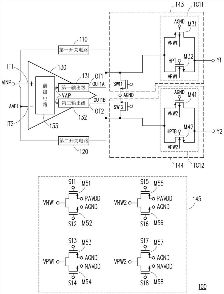
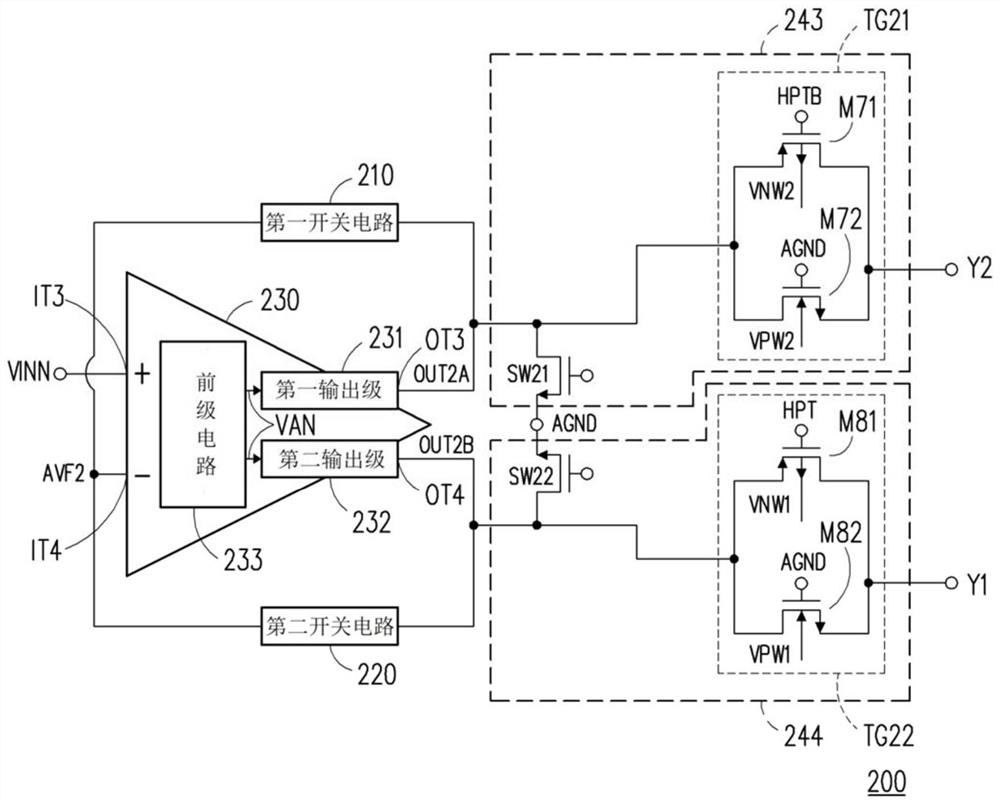
[0065]Figure 1A It is a circuit diagram of a buffer circuit shown in accordance with an embodiment of the present invention. Please refer toFigure 1A . The buffer circuit 100 can be used in the source driver of the display device and to generate a positive polarity voltage signal to drive the pixel of the display panel. The buffer circuit 100 can include a first switching circuit 110, a second switching circuit 120, and an operational amplifier 130, but the present invention is not limited thereto. The operational amplifier 130 has a first input IT1, a second input IT2, a first output OT1, and a second output OT2. The operational amplifier 130 can include a front stage circuit 133, a first output stage 131, and a second output stage 132. The front stage circuit 133 is coupled to the first input IT1 to receive the input signal Vinp, and couple the second input IT2 to receive the feedback signal AVF1, and to generate an amplified signal VAP, where the input signal Vinp is a voltage si...


PUM


Abstract

A buffer circuit includes an operational amplifier, first and second switch circuits. The operational amplifier has first and second input terminals, first and second output terminals. The operational amplifier includes a front stage circuit, a first and a second output stage. The front-stage circuit is coupled to the first input end to receive the input signal, coupled to the second input end to receive the feedback signal, and generates an amplified signal. The first output stage is coupled between the previous stage circuit and the first output terminal, and generates a first output signal according to the amplified signal to drive the first load. The second output stage is coupled between the previous stage circuit and the second output terminal, and generates a second output signal according to the amplified signal to drive the second load. The first switch circuit is coupled between the first output terminal and the second input terminal. The second switch circuit is coupled between the second output terminal and the second input terminal. When the first switch circuit is turned on and the first output stage generates the first output signal to drive the first load, the second switch circuit is turned off and the second output stage is disabled.

Description

Technical field[0001]The present invention relates to a buffer circuit, and more particularly to a buffer circuit of a highly revision rate.Background technique[0002]The panel of the liquid crystal display device comprises a plurality of liquid crystal display units (LQUID CRYSTAL CELL). It is now known that the liquid crystal layer in the liquid crystal display unit is applied for a long time, which causes the charge ion to remain in the liquid crystal layer and the alignment film interface to generate an internal electric field. This may result in a change in the light penetration characteristics of the liquid crystal molecules, so that the liquid crystal panel is irreparable. Therefore, the source driver of the liquid crystal display device typically causes the liquid crystal molecules to be damaged by continuously applying the same polarity by continuously being continuously applied to the driving voltage of the liquid crystal display unit.[0003]In detail, in order to meet the n...

Claims


Application Information

Patent Timeline
Patent Type & Authority Patents(China)
IPC IPC(8): G09G3/36
Inventor 刘立伟陈彦渊黄柏文庄凯杰邓至刚
Owner ILI TECHNOLOGY CORPORATION
Learn More