AI technical title is built by PatSnap AI team. It summarizes the technical point description of the patent document.
A technology for transmissions and motor vehicles, applied in the field of drive trains, can solve the problems of small axial structure length and the like
Inactive Publication Date: 2019-06-18
ZF FRIEDRICHSHAFEN AG
View PDF6 Cites 0 Cited by
Summary
Abstract
Description
Claims
Application Information
AI Technical Summary
This helps you quickly interpret patents by identifying the three key elements:
Problems solved by technology
Method used
Benefits of technology
Problems solved by technology
The axial structural length of such transmissions is kept as small as possible, since the available structural space in the vehicle between the drive motor and the body or chassis is limited
Method used
Image
Click on the blue label to locate the original text in one second.
Reading with bidirectional positioning of images and text.
Examples
Embodiment Construction
[0030] specific implementation plan
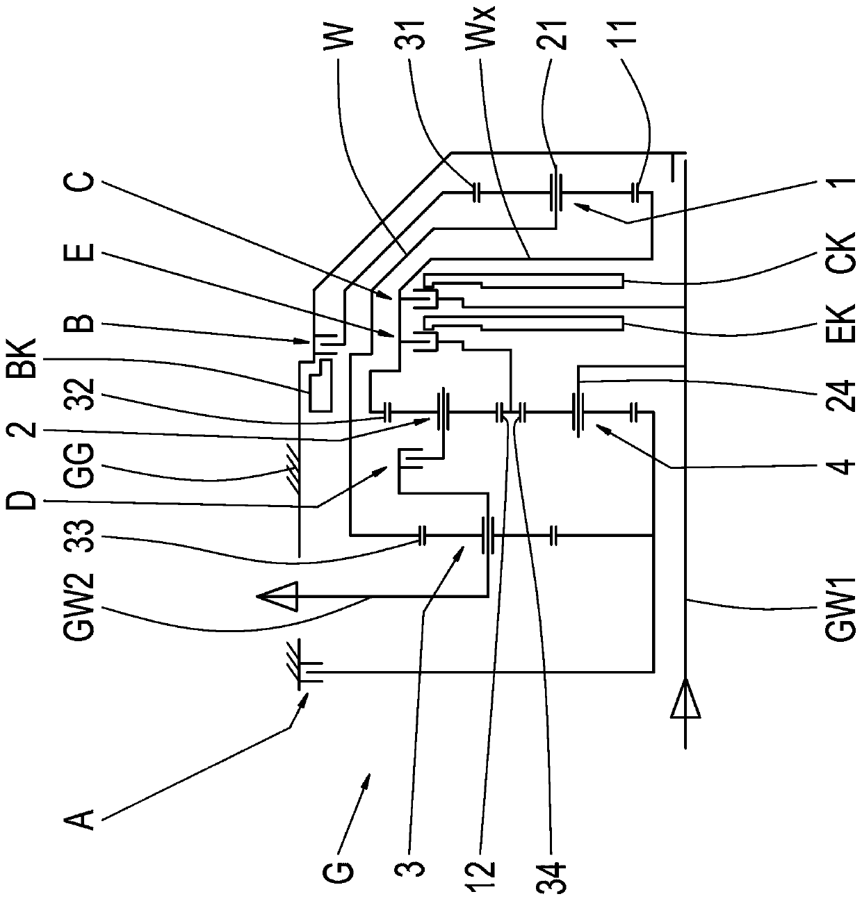
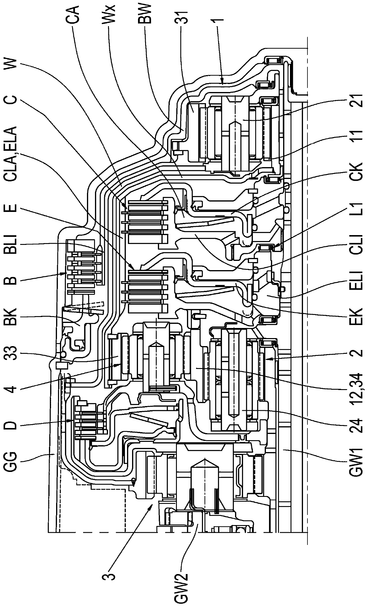
[0031] figure 1 A schematic diagram of a transmission G according to the invention is shown. The transmission G has an input shaft GW1 , an output shaft GW2 , a first planetary gear set 1 , a second planetary gear set 2 , a third planetary gear set 3 and a fourth planetary gear set 4 . The fourth planetary gear set 4 is arranged radially within the second planetary gear set 2 . The planetary gear sets 1, 2, 3, and 4 are all constructed as negative planetary gear sets.
[0032] Transmission G's figure 1 The left side facing transmission G has access to figure 1The end side of the interface of the drive unit outside the transmission is not shown. The third planetary gear set 3 has the shortest axial spacing of the fourth planetary gear set 1 , 2 , 3 , 4 relative to the end side, while the first planetary gear set 1 has the fourth planetary gear set 1 , 2 , 3, 4 relative to the maximum axial spacing of the end side. The second and four...
PUM
Abstract
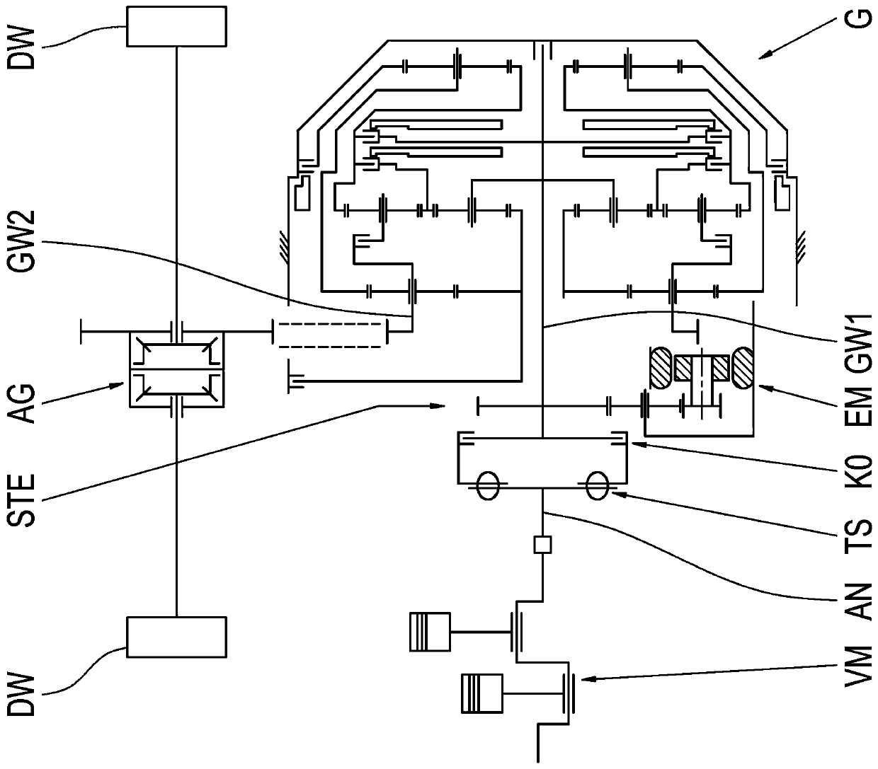
The invention relates to a transmission (G) for a motor vehicle, comprising a drive train oriented transversely to the direction of travel of the motor vehicle, the transmission (G) comprising at least two gear-forming planetary gear sets (1, 2), at least one brake (B) and two clutches (C, E), wherein the first clutch (C) is connected with a first element (11) of the first planetary gear set (1),the second clutch (E) is connected to at least one element (12, 32) of the second planetary gear set (2), and the brake (B) is connected with a second element (31) of the first planetary gear set (1).The two clutches (C, E) are axially arranged between the first and second planetary gear sets (1, 2), the second clutch (E) being arranged axially directly adjacent to the second planetary gear set (2), and the first planetary gear set (1), out of all of the gear-forming planetary gear sets (1, 2, 3, 4) of the transmission (G), has the largest axial distance from the front side of the transmission (G), that has an interface for connecting the transmission (G) to a drive unit (VM) on the outside of the transmission. The two clutches (C, E) are arranged axially directly adjacent to each other,and the brake (B) is arranged, at least in sections, radially outside the second clutch (E), The invention also relates to a drive train for a motor vehicle comprising such a transmission (G).
Description
technical field [0001] The invention relates to a transmission of a motor vehicle and a drive train of a motor vehicle with such a transmission. A transmission here refers in particular to a multi-gear transmission, in which a plurality of gears, ie fixed transmission ratios between the input shaft and the output shaft of the transmission, can be shifted preferably automatically via shift elements. The switching element is here, for example, a clutch or a brake. Such transmissions are used in particular in motor vehicles in order to suitably adapt the rotational speed and torque output characteristics of the drive unit to the driving resistance of the vehicle. Background technique [0002] The applicant's patent application DE 10 2005 014 592 A1 shows numerous variants of a multi-speed transmission for a vehicle with a drive motor mounted transversely to the direction of travel and shaft-parallel drive and output. The overall axial length of such transmissions is kept as s...
Claims
Application Information
Patent Timeline
Application Date:The date an application was filed.
Publication Date:The date a patent or application was officially published.
First Publication Date:The earliest publication date of a patent with the same application number.
Issue Date:Publication date of the patent grant document.
PCT Entry Date:The Entry date of PCT National Phase.
Estimated Expiry Date:The statutory expiry date of a patent right according to the Patent Law, and it is the longest term of protection that the patent right can achieve without the termination of the patent right due to other reasons(Term extension factor has been taken into account ).
Invalid Date:Actual expiry date is based on effective date or publication date of legal transaction data of invalid patent.

