Eureka AIR delivers breakthrough ideas for toughest innovation challenges, trusted by R&D personnel around the world.

Stamping equipment for improving material utilization rate and operation method thereof

A technology of stamping equipment and utilization rate, applied in the field of stamping equipment to improve the utilization rate of materials, can solve the problems of reduced working area, low utilization rate of raw materials, unstable raw materials, etc., and achieves high utilization rate, reduced manpower operation, and good stability. Effect

Active Publication Date: 2019-06-21
WANXIANGQIANCHAO CO LTD +1
View PDF9 Cites 1 Cited by
  • Summary
  • Abstract
  • Description
  • Claims
  • Application Information

AI Technical Summary

Problems solved by technology

[0003] At present, in the process of raw material feeding, the stamping equipment on the market will limit the two sides and the two sides of the upper surface of the raw material in order to maintain the stability of the raw material feeding, although this can make the stability of the raw material movement better. , but during the stamping operation, the working area of ​​the upper die on the raw material is reduced, and the utilization rate of the raw material is low; if the two sides and the two sides of the upper surface of the raw material are not limited, the raw material is easily out of place during the feeding process. Stablize

Method used


Image

  • Stamping equipment for improving material utilization rate and operation method thereof
  • Stamping equipment for improving material utilization rate and operation method thereof
  • Stamping equipment for improving material utilization rate and operation method thereof

Examples


Embodiment 1

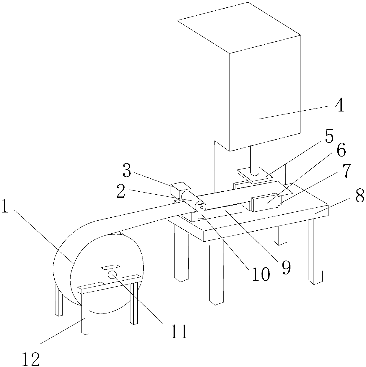
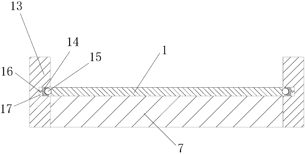
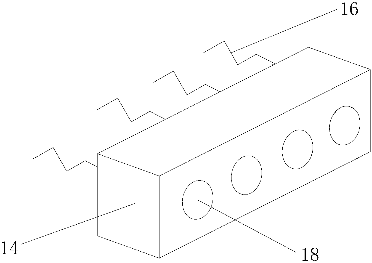
[0022] Such as figure 1 , 2 As shown in , 3, a stamping device for improving the utilization rate of materials includes a feeding part and a stamping part, the feeding part includes a coil rack 12, and the coil rack 12 is provided with a coil motor 11 for driving the coil 1 to rotate The coil material 1 is set on the output shaft of the coil material motor 11, and the coil material 1 can be driven to rotate when the coil material motor 11 is started. A support platform 9 is arranged on the side close to the coil material 1, a rolling shaft 2 is arranged above the support platform 9, a gap for the coil material 1 to pass is provided between the rolling shaft 2 and the support platform 9, and one side of the rolling shaft 2 A support plate 10 is hinged, and the support plate 10 is fixed on the workbench 8 and can support the rolling shaft 2. The other side of the rolling shaft 2 is connected with a driver 3 for driving the rolling shaft 2 to rotate. The finale shaft 2 rotates,...


PUM


Abstract

The invention relates to the technical field of stamping equipment, in particular to stamping equipment for improving material utilization rate and an operation method thereof. The stamping equipmentfor improving the material utilization rate comprises a feeding part and a stamping part, wherein the feeding part comprises a roll material frame; a roll material motor used for driving the roll material to rotate is arranged on the roll material frame; the stamping part comprises a working table; a press machine is arranged on the working table; a supporting table is arranged on one side, closeto the roll material, of the working table; a rolling shaft is arranged above the supporting table; a supporting plate is hinged to one side of the rolling shaft; a driver used for driving the rollingshaft to rotate is connected to the other side of the rolling shaft; a lower die is arranged on one side, away from the roll material, of the supporting table and located on the working table; an upper die matching with the lower die is arranged on the press machine; and anti-deviation devices used for preventing deviation generated when the roll material moves are arranged on the two sides of the lower die. According to the stamping equipment for improving material utilization rate and the operation method thereof, the materials move well stably during feeding, and the utilization rate of the materials is high.

Description

technical field [0001] The invention relates to the technical field of stamping equipment, in particular to a stamping equipment for improving material utilization and an operation method thereof. Background technique [0002] Stamping is a method of forming and processing workpieces (stamping parts) of required shape and size by applying external force to plates, strips, pipes and profiles by presses and molds to cause plastic deformation or separation. Compared with castings and forgings, stamping parts have the characteristics of thinness, uniformity, lightness and strength. Stamping can produce workpieces with ribs, ribs, undulations or flanges that are difficult to manufacture by other methods to increase their rigidity. [0003] At present, in the process of raw material feeding, the stamping equipment on the market will limit the two sides and the two sides of the upper surface of the raw material in order to maintain the stability of the raw material feeding, althou...

Claims


Application Information

Patent Timeline
Patent Type & Authority Applications(China)
IPC IPC(8): B21D22/02B21D43/08B21D1/02
Inventor 过海宋诗英
Owner WANXIANGQIANCHAO CO LTD
Why Eureka
Eureka Blog
Learn More