Backrest angle adaptive adjustment mechanism for seat of high-speed railway
A technology of adjusting mechanism and angle adjustment, which is applied in the directions of seats, railway car body parts, transportation and packaging, etc., can solve the problems of occupying the time and energy of high-speed train crew members, affecting the comfort of passengers in the rear seats, and affecting the riding order of high-speed railways. , to achieve the effect of reliable structure, convenient reset and convenient maintenance
- Summary
- Abstract
- Description
- Claims
- Application Information
AI Technical Summary
Problems solved by technology
Method used
Image
Examples
Embodiment 1
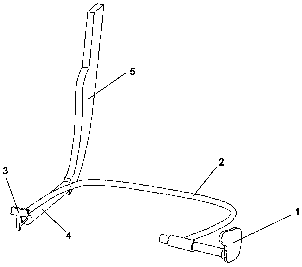
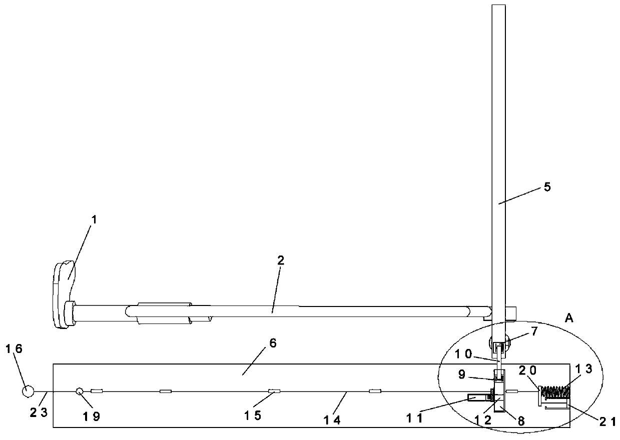
[0052] An adaptive adjustment mechanism for a backrest angle of a high-speed rail seat, the adjustment mechanism includes a backrest angle limiting mechanism and a reset mechanism.
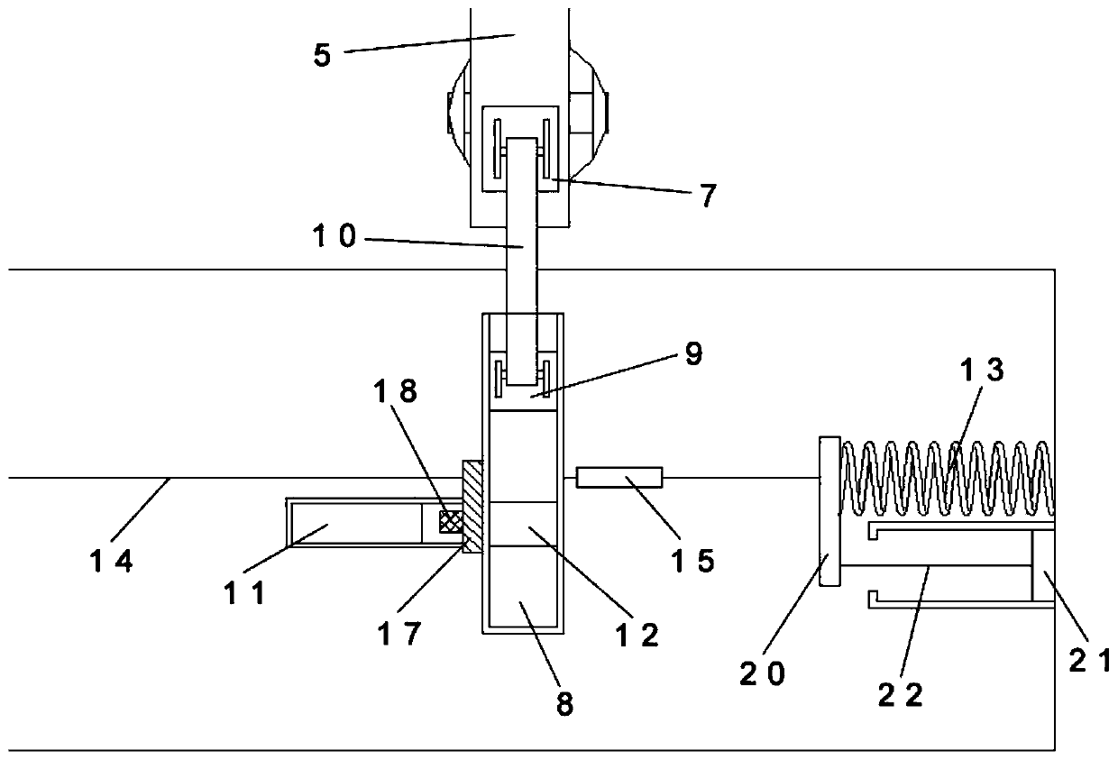
[0053] combine Figure 2-3 , the backrest angle limiting mechanism includes an angle opening module and an angle locking module.
[0054] The angle expansion module includes a fixed block 7 , a connecting shaft 10 , a slide block 9 and an angle adjustment slideway 8 .
[0055] The angle adjustment slideway 8 is provided with the upper part of the back of the base 6, and the slide block 9 is slidably arranged in the slideway of the angle adjustment slideway 8; the fixed block 7 is fixed on the lower part of the backrest connecting plate 5 back; The two ends are respectively hinged on the outside of the fixed block 7 and the slide block 9 through connecting ears.
[0056] In the process of seat back adjustment, with the backrest connecting plate 5 leaning back, the fixed block 7 pushes the slider ...
Embodiment 2
[0061] On the basis of the first embodiment, the specific structure of the reset mechanism is further limited.
[0062] The reset mechanism includes a reset spring 13 , a push plate 20 , a push rod 22 , a reset button 21 , a pull rod 14 , a fixed sleeve 15 , a reset slider 17 , an adapter ring 19 , a pull wire 23 and a pull ring 16 .
[0063] One end of the return spring 13 is fixed on the inner edge of one side of the base 6 , and the return spring 13 and the locking slideway 11 are respectively located on both sides of the angle adjustment slideway 8 . The other end of the back-moving spring 13 is connected to one side of the push plate 20, and the other end of the push plate 20 is connected to one end of the pull rod 14, and the other end of the pull rod 14 slides through the bottom of the angle adjustment slideway 8, and is placed on the pull rod. An adapter ring 19 is formed at the end of 14, and a pull wire 23 is connected to the adapter ring 19, and the pull wire 23 pas...
Embodiment 3
[0073] On the basis of Embodiments 1 and 2, in the seat distribution of the high-speed rail seat second-class car 2+3, three seats are connected to illustrate the setting method of the reset device in the state of row seats.
[0074] In this embodiment, the structures of the seat body, the backrest angle adjustment module and the backrest angle limiting mechanism among the three seats are all the same as those in the above-mentioned embodiments, and will not be repeated here.
[0075] see Figure 7 , the inner side of the inner side of the base of the innermost seat is connected to one end of the return spring 13, the other end of the return spring 13 is connected to one side of the push plate 20, and the other end of the push plate 20 is connected to one end of the pull rod 14, The other end of the pull rod 14 slides through the bottom of the angle adjustment slideways 8 of the three seats respectively, extends into the outermost seat base 6, and passes through the backrest a...
PUM
 Abstract
Description
Claims
Application Information
 - R&D
- Intellectual Property
- Life Sciences
- Materials
- Tech Scout
- Unparalleled Data Quality
- Higher Quality Content
- 60% Fewer Hallucinations
Browse by: Latest US Patents, China's latest patents, Technical Efficacy Thesaurus, Application Domain, Technology Topic, Popular Technical Reports.
© 2025 PatSnap. All rights reserved.Legal|Privacy policy|Modern Slavery Act Transparency Statement|Sitemap|About US| Contact US: help@patsnap.com


