Protein separation and extraction device

A protein separation and extraction device technology, applied in the field of protein separation and extraction devices, can solve problems such as low separation efficiency and high viscosity, and achieve the effects of promoting separation and extraction, promoting material movement, and facilitating separation of impurities

Inactive Publication Date: 2019-06-21
安庆市汇智科技咨询服务有限公司
View PDF0 Cites 1 Cited by
  • Summary
  • Abstract
  • Description
  • Claims
  • Application Information

AI Technical Summary

Problems solved by technology

[0005] However, in the existing protein extraction and separation process, due to the high viscosity of proteins and other substances, the efficiency of purely relying on natural separation during separation and extraction is too low

Method used


Image

  • Protein separation and extraction device
  • Protein separation and extraction device
  • Protein separation and extraction device

Examples


Embodiment 1

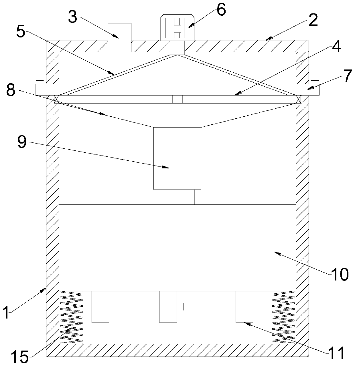
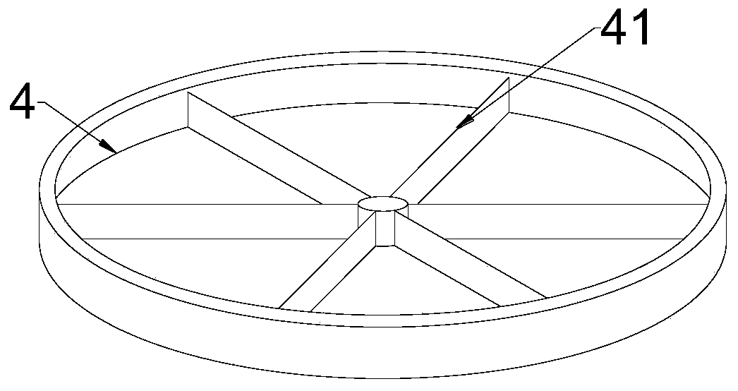
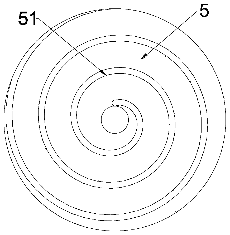
[0028] see Figure 1~4 , in an embodiment of the present invention, a protein separation and extraction device includes a housing 1, an impurity removal mechanism for removing material impurities and a separation structure 10 for extracting and separating proteins, and the lower end of the impurity removal mechanism passes through a flow guide cover 8 It communicates with the material guide pipe 9 and the separation structure 10. The impurity removal mechanism is connected in the housing 1 through rotation. The impurity removal mechanism is also connected with a rotating ring 4, and a fan blade 41 is connected inside the rotating ring 4.

[0029] The upper end of the housing 1 is assembled and connected with an upper cover 2, and the upper cover 2 is fixed on the upper end of the housing 1 by riveting; the upper cover 2 is provided with a feed pipe 3 and a first motor that drives the impurity removal mechanism to rotate 6.

[0030] The impurity removal mechanism includes a fi...

Embodiment 2

[0034] see Figure 5-6 , in the embodiment of the present invention, a protein separation and extraction device, because the viscosity of the protein material is relatively high, if the separation and extraction only rely on gravity, the efficiency is too low, so on the basis of Example 1, the separation structure 10 The upper end is welded with a lifting frame 12, and a through slot is provided through the lifting frame 12, and racks are embedded symmetrically on both sides of the through slot; the inner wall of the housing 1 is also connected with a second motor 13, and the first The periphery of the output end of the second motor 13 is fixedly connected with an incomplete gear 14, and the incomplete gear 14 is located between the racks in the lifting frame 12, and the incomplete gear 14 meshes with the racks on both sides respectively. Transmission, the incomplete gear 14 is a half gear. Start the second motor 13 to drive the incomplete gear 14 to rotate, and the incomplet...


PUM


Abstract

The invention discloses a protein separation and extraction device which comprises a shell, an impurity removal mechanism and a separation structure, wherein the impurity removal mechanism is used forremoving material impurities, the separation structure is used for extracting and separating proteins, the lower end of the impurity removal mechanism is communicated with the separation structure through a flow guide cover and a guide pipeline, the impurity removal mechanism is rotatably connected into the shell and further connected with a rotating ring, and fan blades are connected into the rotating ring. A filter screen can be matched with the design of flow guide blades, the impurities intercepted on the surface of the filter screen can be thrown away in a rotating manner during rotation, impurity separation is facilitated, and the fan blades in the rotating ring can form top-down airflow when the rotating ring and the filter screen synchronously rotate, so that subsequent separation, extraction and processing are promoted. A second motor is started to drive an incomplete gear to rotate, the incomplete gear are in engaged transmission with racks on two sides, a hoisting frame andthe separation structure can be driven to continuously lift up and down, and protein separation and extraction are promoted by shaking.

Description

technical field [0001] The invention relates to the field of biotechnology, in particular to a protein separation and extraction device. Background technique [0002] The separation and extraction of proteins is a challenging task, and the separation is mainly carried out according to five aspects of protein molecular size, solubility, charge, adsorption properties, and biological affinity for ligand molecules. [0003] Usually, proteins are mixtures with complex components, and some components in the mixture are unstable, preheated or easily deformed and inactivated by certain solvents, so traditional separation techniques such as distillation and solvent extraction are not suitable for their separation purification. In addition, proteins obtained by precipitation, gradient centrifugation, salting out, etc. often contain impurities. To remove these impurities while maintaining the biological activity of the protein, such as the catalytic activity of the enzyme, it is neces...

Claims


Application Information

Patent Timeline
IPC IPC(8): C07K1/34C07K1/14
Inventor 徐春生陈伟
Owner 安庆市汇智科技咨询服务有限公司
Why Eureka
Try Eureka