
Bridge cast-in-place concrete anti-collision guardrail construction device and method

An anti-collision guardrail and construction device technology, applied in bridges, bridge materials, bridge construction, etc., can solve the problems of limited working radius of cranes, reduced construction efficiency, low safety, etc., and achieve high construction efficiency, fast construction, and beautiful linear shape. Effect

Active Publication Date: 2021-10-01
CHINA FIRST METALLURGICAL GROUP
View PDF0 Cites 0 Cited by
  • Summary
  • Abstract
  • Description
  • Claims
  • Application Information

AI Technical Summary

Problems solved by technology

[0002] In the construction of traditional bridge anti-collision barriers, the installation and removal of the guardrail formwork requires the use of cranes, and the working radius of the crane is limited, so it needs to be constantly shifted to meet the construction requirements, which greatly reduces the construction efficiency
In addition, the connection between the formwork is generally connected by bolts. When installing the connecting bolts and pull rods of the outer formwork, the operator needs to work outside the guardrail, which is low in safety.

Method used


Image

  • Bridge cast-in-place concrete anti-collision guardrail construction device and method
  • Bridge cast-in-place concrete anti-collision guardrail construction device and method
  • Bridge cast-in-place concrete anti-collision guardrail construction device and method

Examples


Embodiment Construction

[0030] It should be understood that the specific embodiments described here are only used to explain the present invention, not to limit the present invention.

[0031] It should be noted that, in the description of the present invention, the terms "horizontal", "vertical", "upper", "lower", "front", "rear", "left", "right", "vertical", The orientation or positional relationship indicated by "horizontal", "top", "bottom", "inner", "outer", etc. is based on the orientation or positional relationship shown in the drawings, and is only for the convenience of describing the present invention and simplifying the description, and It is not to indicate or imply that the device or element referred to must have a particular orientation, be constructed in a particular orientation, or operate in a particular orientation, and thus should not be construed as limiting the invention. In addition, the terms "first", "second", etc. are used for descriptive purposes only, and should not be cons...


PUM


Abstract

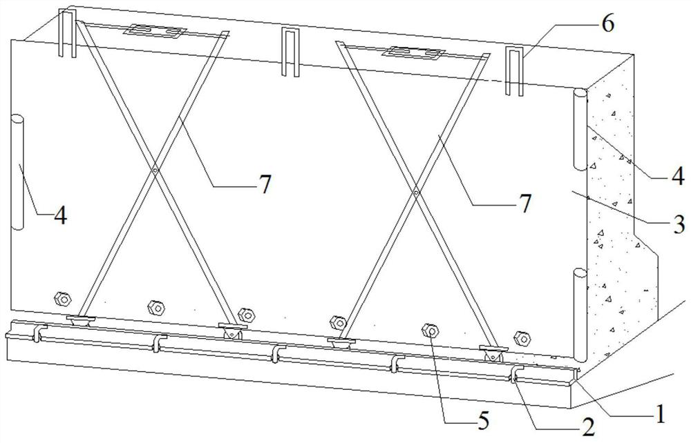
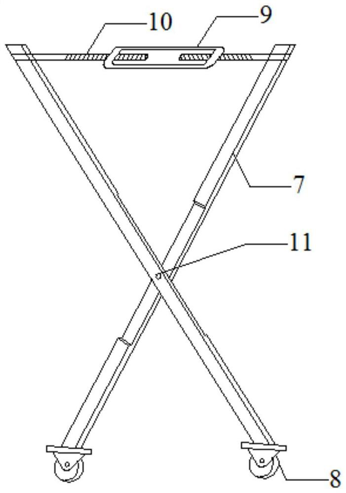
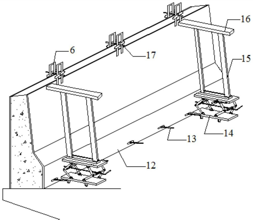
The invention discloses a bridge cast-in-place concrete anti-collision guardrail construction device, which includes an inner formwork, an outer formwork, an inner formwork jacking bracket and an outer formwork jacking support, and the outer formwork jacking support includes a first vertical rod and a second hinged joint. Two vertical rods, the rotating shaft at the joint of the first vertical rod and the second vertical rod is fixed with the outer formwork, the bottoms of the first vertical rod and the second vertical rod are equipped with rollers, and the tops of the first vertical rod and the second vertical rod are A screw rod is provided, and the screw rods of the first vertical rod and the second vertical rod are connected by a rotating handle; the lifting bracket of the inner mold includes a bottom bracket and a support frame, and a walking wheel is arranged under the bottom bracket, and the top of the inner formwork and the outer formwork are set There is tie rod support, and the top tie rod passes through the tie rod support of the inner formwork and the outer formwork to connect the two tops, and the bottom of the inner formwork and the outer formwork are connected through a pair of drawing rods. The bridge cast-in-place concrete anti-collision guardrail construction device proposed by the invention is safe, reliable and has high construction efficiency.

Description

technical field [0001] The invention relates to the technical field of bridge construction, in particular to a construction device and method for cast-in-place concrete anti-collision barriers for bridges. Background technique [0002] In the traditional construction of bridge anti-collision guardrails, the installation and removal of the guardrail formwork requires the use of cranes, but the working radius of the crane is limited, and it needs to be constantly shifted to meet the construction requirements, which greatly reduces the construction efficiency. In addition, the connection between the formwork is generally connected by bolts. When installing the connecting bolts and the tension rods of the outer formwork, the operator needs to work in the air outside the guardrail, and the safety is low. Contents of the invention [0003] The main purpose of the present invention is to provide a safe, reliable and high-efficiency bridge cast-in-place concrete anti-collision gua...

Claims


Application Information

Patent Timeline
Patent Type & Authority Patents(China)
IPC IPC(8): E01D19/10E01D21/00E01D101/24
Inventor 陈远厚兴平刘长江高旭周恋孙锦程
Owner CHINA FIRST METALLURGICAL GROUP
Learn More