Load box gap reinforcing device after self-balancing detection and reinforcing method thereof
A technology of reinforcing device and load box, which is applied in the direction of basic structure test, construction, basic structure engineering, etc., to achieve the effect of improving the success rate, strong affinity and ensuring the consolidation strength
- Summary
- Abstract
- Description
- Claims
- Application Information
AI Technical Summary
Problems solved by technology
Method used
Image
Examples
Embodiment 1
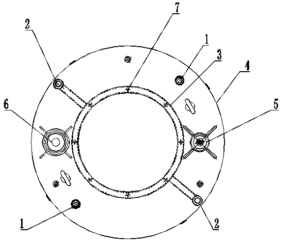
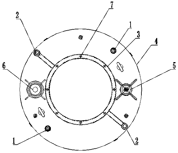
[0025] This embodiment is a gap reinforcement device after a self-balancing test of a load box. The gap reinforcement device after a self-balance test of a load box includes a load box device, a steel cage device, an upper displacement tube 1, a lower displacement tube 2 and a grouting annular circuit tube 3;
[0026] The load box device includes a grouting load box 4, a grouting check valve 5 and a hydraulic pipe 6;
[0027] The grouting annular circuit pipe 3 is fixed on the center of the upper plate of the grouting load box by indirect welding, the centerline of the grouting annular circuit pipe 3 is coaxial with the center of the grouting load box 4, and the diameter is the same as that of the grouting load box 4 The middle hole is the same, the two ends of the grouting annular circuit pipe 3 are respectively connected with the lower displacement pipes 2 arranged symmetrically on both sides of the grouting load box 4 to form an annular passage, and the grouting check valve ...
Embodiment 2
[0035] This embodiment is a grouting reinforcement method in a cylinder of a grouting load box. After the foundation pile self-balancing static load test is completed, the uniformly stirred grout is output through the grouting equipment, enters the grouting pipe, and is directly injected through the grouting check valve 5 In the grouting load box 4, and through the grouting injection pipe of the grouting load box 5, the grout is discharged, and the grout reaches the concentration of the grout return pipe, and then closes the liquid inlet pipe. Stop grouting after pressing for a certain period of time.
[0036] The grouting load box in the cylinder adopts a double liquid circuit structure: the grout return pipe and the grouting pipe. The grouting pipe is connected and sealed with the grouting load box 4 through the grouting check valve 5, and the grouting load box 4 is threaded with the grouting equipment. The connection is sealed. When grouting in the cylinder, the grouting eq...
Embodiment 3
[0038] This embodiment is a grouting reinforcement method outside the cylinder of the grouting load box. After the self-balancing static load test of the foundation pile is completed, the evenly stirred grout enters the lower displacement pipe 2 on one side of the grouting pipe through the output port, and the grout moves along the vertical direction at the same time. The pipeline flow of the grouting pipeline and the grouting annular loop pipe 3 on the side, due to the vertical grouting outside the cylinder, the grouting range is large and the area is widely dispersed. The grouting resistance of the grouting pipeline is getting bigger and bigger, until the coverage radius of grouting is reached, the grouting will stop injecting in this direction, and the grouting will be concentrated in the pipeline direction of the grouting annular loop pipe 3 on the side, and the grouting will continue until the return On the other side of the grout pipe, the lower displacement pipe 2 emits ...
PUM
 Abstract
Description
Claims
Application Information
 - R&D
- Intellectual Property
- Life Sciences
- Materials
- Tech Scout
- Unparalleled Data Quality
- Higher Quality Content
- 60% Fewer Hallucinations
Browse by: Latest US Patents, China's latest patents, Technical Efficacy Thesaurus, Application Domain, Technology Topic, Popular Technical Reports.
© 2025 PatSnap. All rights reserved.Legal|Privacy policy|Modern Slavery Act Transparency Statement|Sitemap|About US| Contact US: help@patsnap.com


