Pump device for delivering a medium

a technology of a pump device and a medium, which is applied in the direction of pump control, rotary/oscillating piston combination, liquid fuel engine, etc., to achieve the effect of slowing down the transfer of the medium

Inactive Publication Date: 2017-03-14
CONTINENTAL AUTOMOTIVE GMBH
View PDF18 Cites 1 Cited by
  • Summary
  • Abstract
  • Description
  • Claims
  • Application Information

AI Technical Summary

Benefits of technology

[0009]This configuration ensures that the pressure produced in the under-vane regions by the retracting vanes is used to extend other vanes. Since the fluid duct is closed during the starting of the vane-type pump, the situation in which pressure built up by the retracting vanes can escape into the pressure region before a pressure is built up in the pressure region is avoided. By virtue of this aspect of the invention, the vanes moved past the suction region are extended during the first revolution of the rotor. As a result, the pump device according to the invention is of particularly simple construction.
[0010]The fluid duct can be closed in both directions in accordance with the operating state of the pump device according to an aspect of the invention if a switchable valve is arranged in the fluid duct.
[0009]This configuration ensures that the pressure produced in the under-vane regions by the retracting vanes is used to extend other vanes. Since the fluid duct is closed during the starting of the vane-type pump, the situation in which pressure built up by the retracting vanes can escape into the pressure region before a pressure is built up in the pressure region is avoided. By virtue of this aspect of the invention, the vanes moved past the suction region are extended during the first revolution of the rotor. As a result, the pump device according to the invention is of particularly simple construction.
[0012]According to another aspect development of the invention, moving parts for closing the fluid duct during the starting of the vane-type pump can be avoided in a simple manner if a temperature-dependent hydraulic resistance is arranged in the fluid duct, wherein the hydraulic resistance is greatest at low temperatures. The hydraulic resistance is preferably designed such that the maximum leakage losses occurring during operation in the under-vane region produce a pressure difference which is clearly below the minimum operating pressure of the pump device. This ensures that the restricted pressure in the under-vane region does not fall below the ambient pressure and is sufficient to extend the vanes. By virtue of the temperature dependence, the hydraulic resistance enables the under-vane region to be decoupled from the pressure region during the starting of the pump device and hence while the medium is still cold, with the result that the under-vane regions of the retracting and of the extending vanes are coupled. Another advantage of this embodiment is that the pressure in the under-vane regions is restricted, thus minimizing the contact pressure of the extending vanes against the cam contour. This reduces friction and wear on the vane-type pump. In the simplest case, the hydraulic resistance is a restrictor. The hydraulic resistance can be used as a replacement for or in addition to the switchable valve or the check valve.
[0013]A contribution to a further reduction in the structural complexity of the pump device is made if the pressure region is arranged at the outlet of the vane-type pump.
[0014]According to another advantageous aspect of to the invention, the vanes can be extended hydraulically in a reliable manner if the pressure region is arranged at the outlet of a second pump. By this embodiment, some of the delivery flow of the second pump can be used to hydraulically extend the vanes of the vane-type pump. By virtue of this embodiment, the pump device according to the invention has two pumps which can be operated independently of one another.
[0015]According to another advantageous aspect of the invention, the second pump allows direct production of a pressure for extending the vanes of the vane-type pump if the second pump is a ring gear pump or is configured as a gear pump. By virtue of the principle involved, such ring gear pumps or gear pumps have fixed teeth, ensuring immediate delivery when the second pump starts, even when the media are cold and viscous.
[0016]According to another advantageous aspect of the invention, envisaged pressures in the under-vane regions can be ensured if the under-vane regions are connected to one another by a groove arranged in a stator, and if the groove has a constriction between the under-vane regions of the extending vanes and the under-vane regions of the retracting vanes. The constriction also acts as a restrictor and slows a transfer of the medium from one under-vane region to the other under-vane region.

Problems solved by technology

However, the disadvantage with the known pump device is that, where the medium is viscous or the vane-type pump is not completely filled with medium, the pressure produced in the under-vane regions by the retracted vanes can escape via the fluid duct.

Method used


Image

  • Pump device for delivering a medium
  • Pump device for delivering a medium
  • Pump device for delivering a medium

Examples


Embodiment Construction

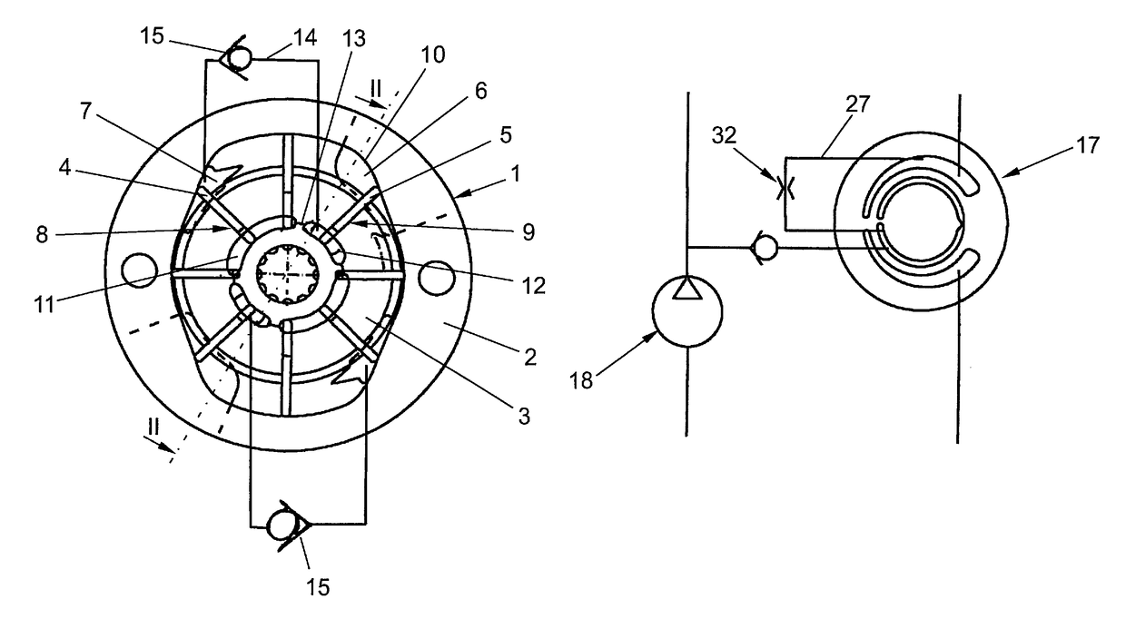
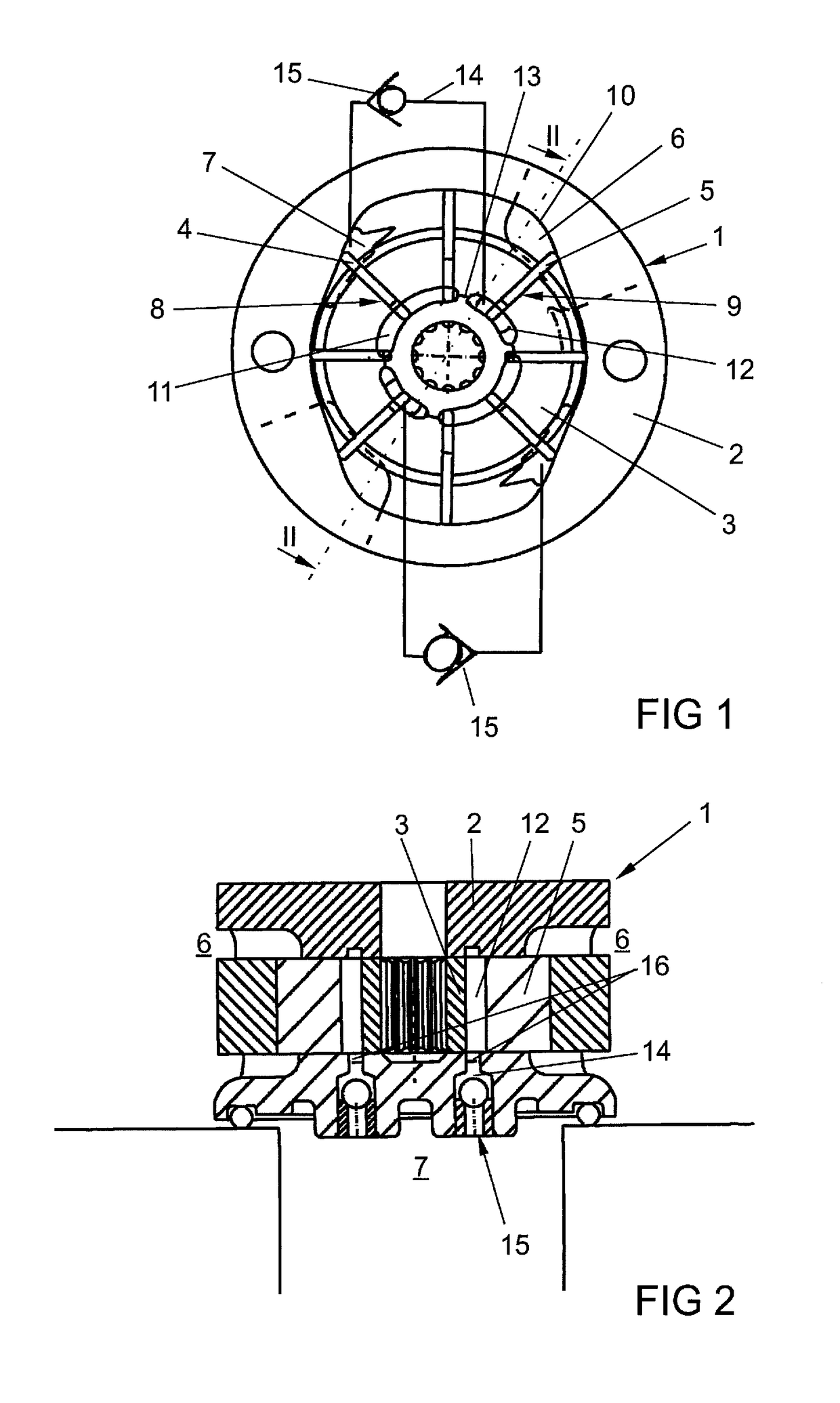
[0023]FIG. 1 shows a pump device having a double-lift vane-type pump 1. The vane-type pump 1 has a rotor 3, which can rotate in a stator 2, and extendable vanes 4, 5. The vane-type pump 1 delivers a medium, e.g. transmission oil, from suction regions 6 to pressure regions 7. The vanes 4, 5 are guided in a radially movable manner in vane slots 8, 9, against a cam contour 10 of the stator 2. The rotor 3 has under-vane regions 11, 12, which are partially connected to one another by constrictions 13. The pressure regions 7 are connected, via fluid ducts 14 with check valves 15 arranged therein, to under-vane regions 12 arranged in the suction region 6. The check valves 15 are aligned in such a way that they shut off in the direction of the pressure region 7. When the rotor 3 rotates counterclockwise, the vanes 4 situated in the pressure region 7 are pressed into the rotor 3, while vanes 5 situated in the suction region 6 are extended. The vanes 4 pressed into the rotor 3 build up a pres...


PUM


Abstract

A pump device having a vane-type pump has a check valve in a fluid duct which leads from a pressure region to an under-vane region. The check valve blocks in the direction of the pressure region, preventing pressure from escaping from the under-vane region into the pressure region during the start-up of the vane-type pump.

Description

CROSS-REFERENCE TO RELATED APPLICATIONS[0001]This is a U.S. national stage of application No. PCT / EP2012 / 070839, filed on 22 Oct. 2012, which claims priority to the German Application No. 10 2011 085 795.8, filed 4 Nov. 2011, the content of both incorporated herein by reference.BACKGROUND OF THE INVENTION[0002]1. Field of the Invention[0003]The invention relates to a pump device for delivering a medium, having a vane-type pump, in which the vane-type pump has a rotor having vanes, which can be extended radially outward out of vane slots in the direction of a cam contour of a stator, and having under-vane regions, which are connected to a pressure region of the pump device by a fluid duct, to enable the under-vane regions to be subjected to pressure to hydraulically extend the vanes, wherein the under-vane regions of the vanes are connected to one another.[0004]2. Related Art[0005]Pump devices of this kind are used in modern motor vehicles to deliver transmission oil and are known in...

Claims


Application Information

Patent Timeline
Patent Type & Authority Patents(United States)
IPC IPC(8): F04C2/344F04C14/06F01C21/08F04C11/00F04C2/10
CPCF04C2/3446F01C21/0863F04C11/006F04C14/06F04C2/10
Inventor BOHM, CHRISTIAN
Owner CONTINENTAL AUTOMOTIVE GMBH
Why Eureka
Try Eureka