
A plug-in box that can be quickly assembled

A plug-in box and fast technology, applied in the direction of fully enclosed busbar device, etc., can solve the problems of manpower and time, limited volume of plug-in plastic parts, and potential safety hazards, so as to save the complicated process, the fixing method is convenient, Reliable effect of fixing

Active Publication Date: 2020-11-03
镇江西格玛电气有限公司
View PDF7 Cites 0 Cited by
  • Summary
  • Abstract
  • Description
  • Claims
  • Application Information

AI Technical Summary

Problems solved by technology

The steps of the entire rear plate processing and the number of stamping dies required are relatively large, resulting in a complicated production process and requiring more man-hours
(3) The fixing plate used to fix the micro-break support frame and the monitoring module support frame in the existing plug-in box adopts two L-shaped plates arranged outwards, and then the support frame is fastened by 4 screws, and at the same time It is also necessary to drill holes and tap on the fixing plate, the process is complicated, and the fixing effect is not stable
(4) The existing micro-break support frame adopts an integrated U-shaped plate, and its size has requirements for the knife edge of the bending machine. If the distance is too short, a small knife edge is required
(5) In the existing monitoring module, the main board and the CT integrated board are installed on different brackets, so when fixing the monitoring module, two brackets need to be used for fixing, which will consume manpower and time during assembly
(7) Moreover, due to the limited volume of the plug-in plastic parts, the gap between the electrical terminals on both sides of the plug-in plastic parts is small, which is easy to cause short-circuit accidents and has potential safety hazards
(8) The locking mechanism on the side plate cannot fix the rotary handle when locked, which is likely to cause misoperation and cause the plug-in box to fall

Method used


Image

  • A plug-in box that can be quickly assembled
  • A plug-in box that can be quickly assembled
  • A plug-in box that can be quickly assembled

Examples


Embodiment Construction

[0044] In order to make the technical solution of the present invention clearer, the present invention will be further described below in conjunction with the accompanying drawings. Any solution obtained by equivalent replacement and conventional reasoning of the technical features of the technical solution of the present invention falls within the protection scope of the present invention.

[0045] In describing the present invention, it is to be understood that the terms "upper", "lower", "front", "rear", "left", "right", "vertical", "horizontal", "top" , "bottom", "inner", "outer" and other indicated orientations or positional relationships are based on the orientations or positional relationships shown in the drawings, and are only for the convenience of describing the invention and simplifying the description, rather than indicating or implying Any device or element must have a specific orientation, be constructed and operate in a specific orientation and therefore should ...


PUM


Abstract

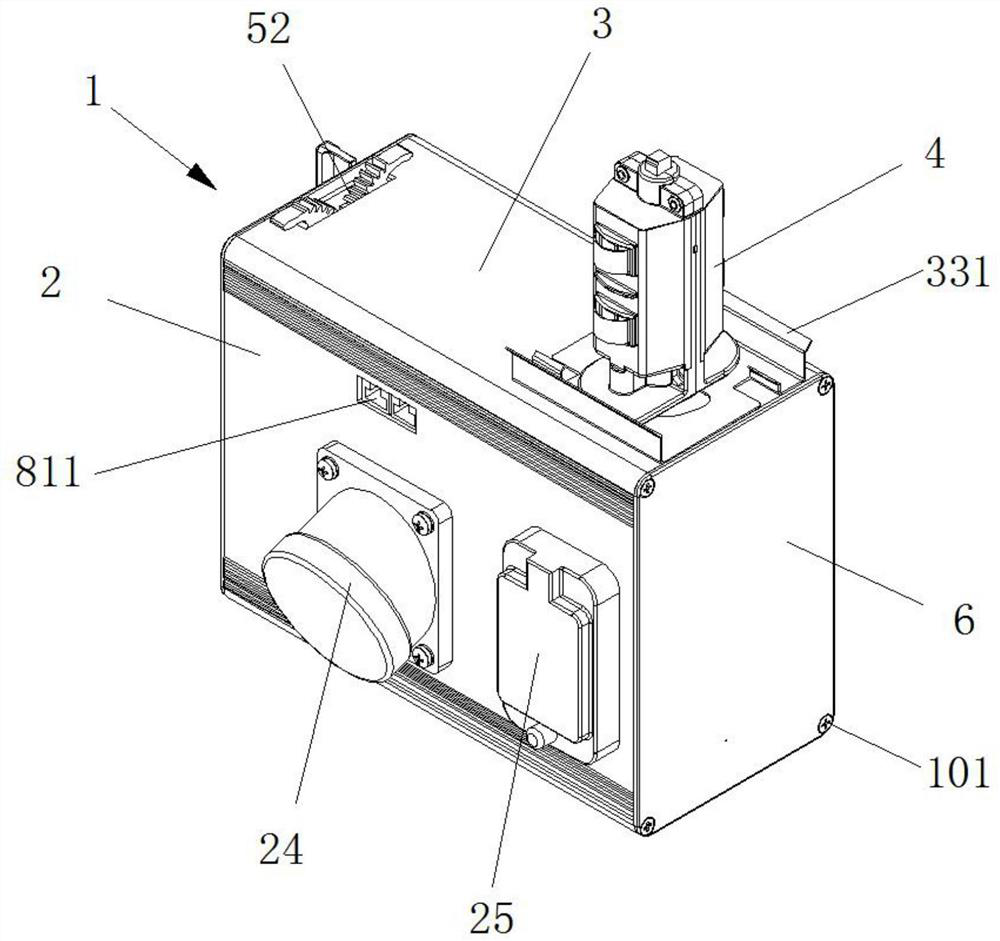
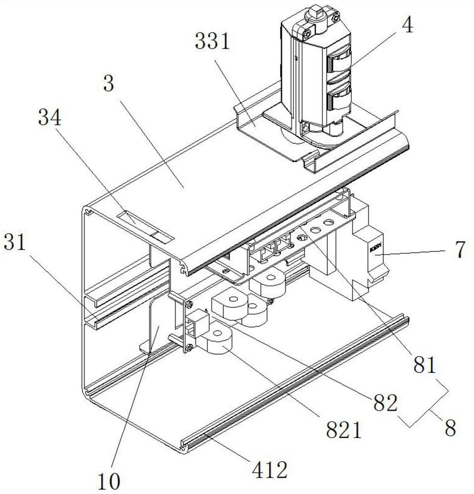
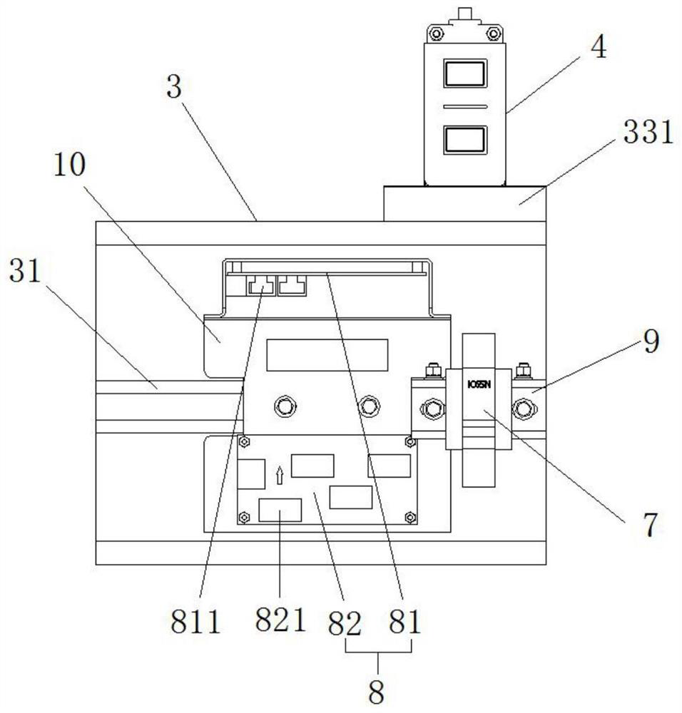
The invention belongs to the technical field of power transmission equipment and particularly relates to a jack box capable of being rapidly assembled. The jack box comprises a box body, a plug connector mounted at the top of the box body as well as a micro circuit breaker and a monitoring module which are mounted in the box body, wherein the box body comprises a front plate, a rear plate, a leftside plate and a right side plate, the front plate is fixed on the opening side of the rear plate, fixing plates are symmetrically arranged on the inner wall in the middle of the rear plate, insert panels are arranged between the fixing plates, a riveting nut is arranged on one side of each insert panel, and a micro circuit breaker support frame and a monitoring module support frame are connectedto the other sides of the insert panels respectively; the plug connector is arranged at the top of the rear plate and comprises a left plugin and a right plugin, and a partition board is arranged on one side, adjacent to the right plugin, of the left plugin; and screw hole grooves are formed in four corners of the inner wall of the rear plate, the left side plate and the right side plate are fixedat two ends of the rear plate through self-tapping locking screws, and additional processing of punching holes for mounting of the side plates on two sides is not required. The left plugin and the right plugin are separated by the partition board, and short-circuit accidents caused by a too small interval between a left plugin terminal and a right plugin terminal are avoided.

Description

technical field [0001] The invention belongs to the technical field of power transmission equipment, and in particular relates to a quick-assembled plug-in box. Background technique [0002] The plug-in box is a mechanical linkage control device with a safety protection function constructed between the box body, the box cover, the bus contact and the shunt circuit breaker, and is used for installation at the bottom of the bus duct. (1) The processing and manufacture of the back plate of the existing plug-in box needs to open a countersunk hole on the back plate profile, so as to be fixed with the side sealing plate with the countersunk screw, so that the processing flow of the back plate profile is more complicated. (2) The RJ45 network cable hole corresponding to the monitoring module is made by stamping with a mold, and its position on the rear panel is fixed. If the installation position of the monitoring module is changed, the stamping mold needs to be opened again. The...

Claims


Application Information

Patent Timeline
Patent Type & Authority Patents(China)
IPC IPC(8): H02G5/08
Inventor 袁华君胡群
Owner 镇江西格玛电气有限公司
Learn More