Penetrative-assembling method for compact type roller bearing structure motor

A kind of rolling bearing and compact technology, which is applied in the field of wearing and fitting of motors with compact rolling bearing structure, can solve the problems of not being able to use the fitting method, and not allowing the load-bearing to be shelved, so as to achieve the effect of avoiding load-bearing and high safety.

Active Publication Date: 2019-06-21
上海电气集团上海电机厂有限公司
View PDF5 Cites 3 Cited by
  • Summary
  • Abstract
  • Description
  • Claims
  • Application Information

AI Technical Summary

Problems solved by technology

[0002] When the stator and rotor of conventional rolling bearing motors are installed, the iron core part of the rotor is allowed to temporarily rest on the stator or the ground, such as figure 1 As shown, the rotor body 230 of some motors is a thin plate structure with a thickness of about 2mm, which is not allowed to be placed on the load-bearing, and the diameter of the connecting disc body 250 on the side of the rotor shaft extension is larger than the inner diameter of the stator 500, so it needs to be worn from the shaft extension end. In addition, the distance between the motor rotor body 230 and the bearing gear is very close, so tools such as jacks cannot be used to support the inner side during installation, so the conventional rolling bearing motor installation method cannot be used

Method used


Image

  • Penetrative-assembling method for compact type roller bearing structure motor
  • Penetrative-assembling method for compact type roller bearing structure motor
  • Penetrative-assembling method for compact type roller bearing structure motor

Examples


Embodiment Construction

[0022] A method for mounting a motor with a compact rolling bearing structure, comprising:

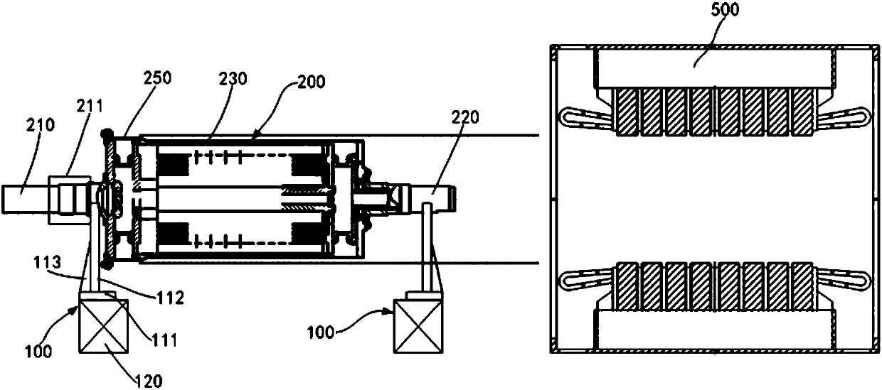
[0023] One, such as figure 1 As shown, the shaft extension end 210 and the non-shaft extension end 220 of the motor rotor 200 are rested on the support frame 100 located on both sides of the axial direction, and the support frame 100 on the shaft extension end side is located at the installation position of the rotor body 230 and the bearing and the end cover. Between 211.

[0024] Wherein, the support frame 100 includes a frame body 110 and a spacer 120 for cushioning under the frame body 110, such as Figure 5 As shown, the frame body 110 includes a base plate 111 and a support plate 112, the base plate 111 is arranged horizontally, the support plate 112 is vertically fixed to the base plate 111, and two reinforcing plates in a right triangle shape are connected between the front and rear sides of the support plate 112 and the base plate 111. Plate 113, two reinforcement plates 113...


PUM


Abstract

The invention discloses a penetrative-assembling method for a compact type roller bearing structure motor. The method comprises the following steps: placing a drive end and a non-drive end of a motorrotor on support frames at two sides of an axial direction; orderly mounting a bearing and an end cover at a bearing and end cover mounting place at the drive end side of the motor rotor; mounting anextended shaft and a connecting sling at the non-drive end of the motor rotor, and performing penetrative-assembling; fixedly connecting an end cover at the drive end side of the motor rotor with a motor stator through a bolt, importing a sling from a non-driven end base window of the motor stator so that the motor rotor is suspended on the sling, and removing the slings at two ends of the motor rotor; orderly mounting the bearing and the end cover at the non-drive end of the motor rotor, and fixedly connecting the end cover and the motor stator through the bolt, and removing the sling imported into the non-drive end base window. The penetrative-assembling method disclosed by the invention is convenient, fast and high in security.

Description

technical field [0001] The invention belongs to the technical field of mounting motors, and in particular relates to a mounting method of a motor with a compact rolling bearing structure. Background technique [0002] When the stator and rotor of conventional rolling bearing motors are installed, the iron core part of the rotor is allowed to temporarily rest on the stator or the ground, such as figure 1 As shown, the rotor body 230 of some motors is a thin plate structure with a thickness of about 2mm, which is not allowed to be placed on the load-bearing, and the diameter of the connecting disc body 250 on the side of the rotor shaft extension is larger than the inner diameter of the stator 500, so it needs to be worn from the shaft extension end. In addition, the distance between the motor rotor body 230 and the bearing gear is very close, so tools such as jacks cannot be used to support the inner side during installation, so the conventional rolling bearing motor installa...

Claims


Application Information

Patent Timeline
Patent Type & Authority Applications(China)
IPC IPC(8): H02K15/00H02K15/16H02K15/02
Inventor 王君姚群
Owner 上海电气集团上海电机厂有限公司
Why Eureka
Try Eureka