Centrifuge adapter

a technology for centrifuges and adapters, which is applied in the direction of centrifuges, laboratory glassware, separation processes, etc., can solve the problems of difficult to break vacuum, substantial resuspension of separated sample materials, and problems that remain

Inactive Publication Date: 2006-10-10
BECKMAN COULTER INC
View PDF18 Cites 1 Cited by
  • Summary
  • Abstract
  • Description
  • Claims
  • Application Information

AI Technical Summary

Benefits of technology

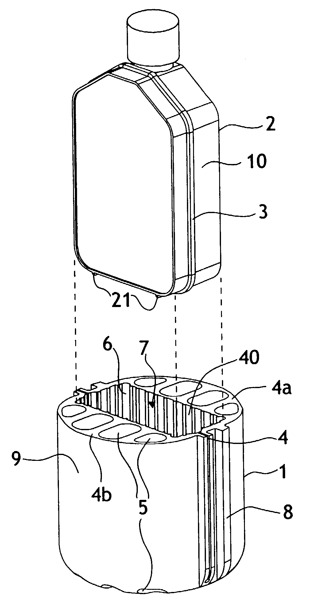
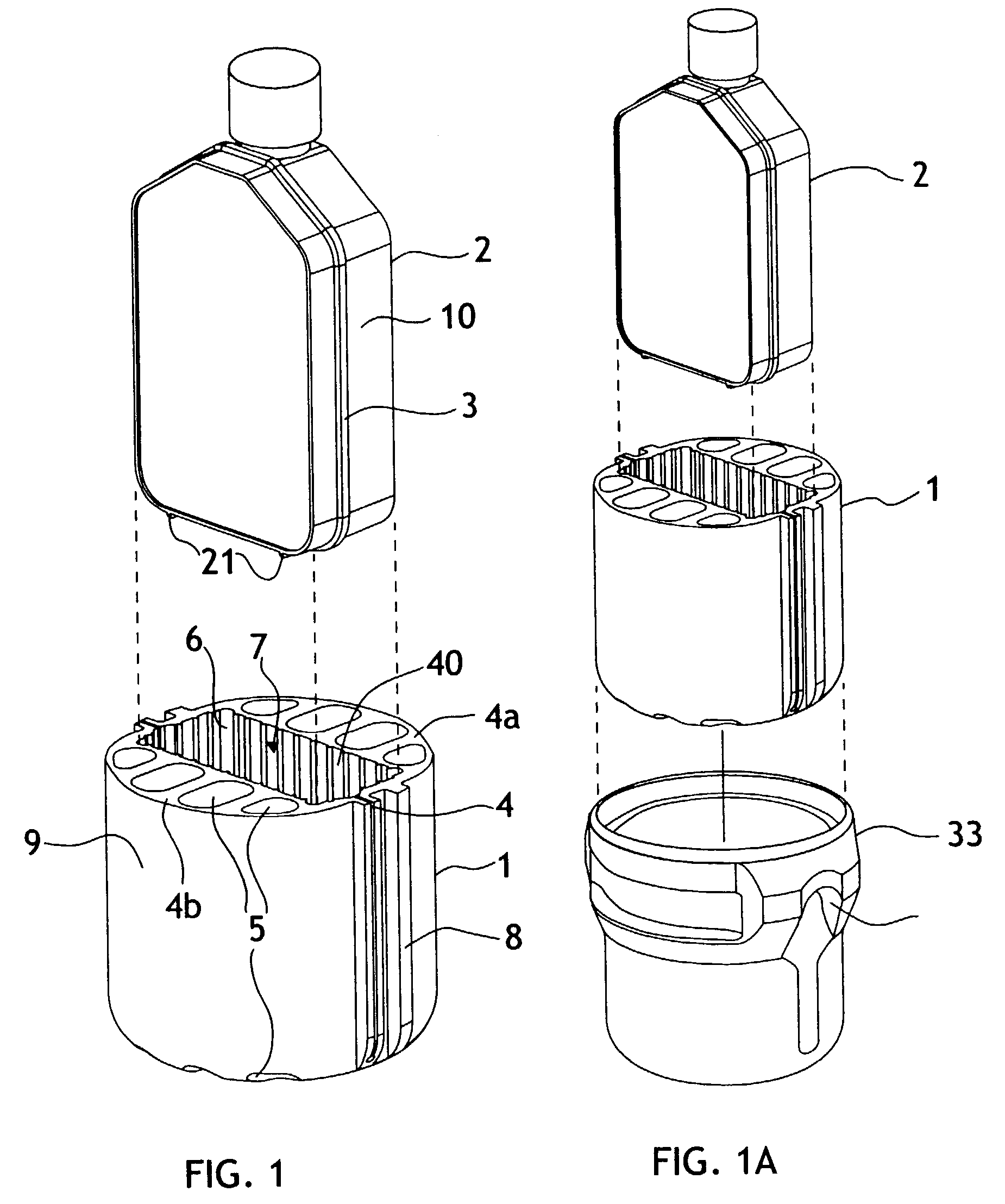
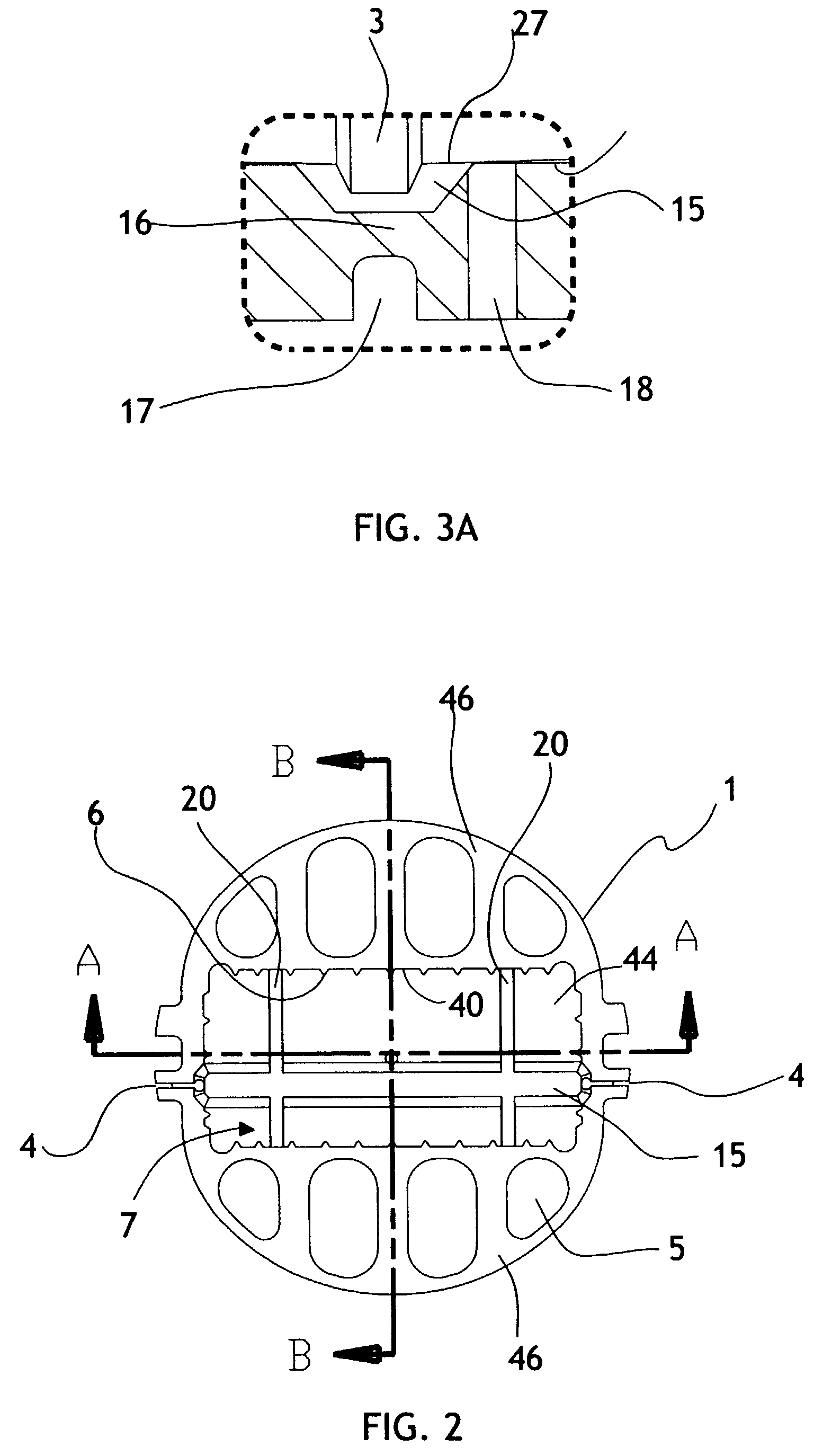
[0012]The above objects have been achieved with an adapter to hold a sample container having features that allow for efficient separation. In various embodiments these features support the sample container, accommodate raised features on the outer surface of sample containers and allow a container to be spun and removed from an adapter with minimal disturbance of the separated sample material. In one embodiment a recessed portion of each adapter section are brought together into alignment by the hinge such that the recessed portions form a pocket which holds a centrifuge container. The sections are separated by a slit extending from the open top of the pocket to a location proximate to the bottom of the pocket. The walls of the pocket have ribs which run down the length of the wall of the pocket, providing support to a container wall inserted in the pocket.
[0013]The present adapter may include a number of features. A first such feature is ribbing on the exterior surface of the adapter that contacts the rotor device into which the adapter is inserted. Exterior ribbing will reduce friction during extraction of the adapter. A second feature is through holes extending through the adapter sections to reduce adapter mass and ease extraction of the adapter from a rotor device by breaking any vacuum between the rotor device and the adapter. A third feature is a vent hole that passes through the bottom of the sample container pocket to break any suction between the bottom of the adapter and a rotor device used with the present adapter. A fourth feature is a hinge groove to reduce the thickness of material at the hinge location, and to increase the durability of the hinge. A fifth feature is a slit that may include a cutout at the lowest portion of the slit, which also would add to the durability of the hinge. A sixth feature is an orientation indicia to indicate to a user the proper alignment of the sample container to the adapter and the adapter with the rotor device.
[0014]A seventh feature is the presence of one or more grooves in the interior of the pocket to prevent force load from concentrating on a ridge, seam, leg, or other protrusion from the exterior surface on the sample container. For cell culture flask adapters, the relatively delicate seam is fit into an adapter seam groove, such that the centrifugal force is distributed onto the walls of the flask. These walls are supported by the pocket ribs, thus preventing seam failure. The legs of the sample container and stacking ridges on the edges of the sides of the sample container also may be accommodated in a recess. The ribs extend to prevent the load from bearing onto the ridges or legs and instead allow the load to be distributed across the surface of the sides or bottom of the flask during centrifugal rotation. An eighth feature of the present invention is handles, which may be used to compress the sections of the adapter together to aid in extraction of the adapter from a centrifuge rotor.

Problems solved by technology

In designing of centrifuge adapters, one issue of concern is preventing agitation of the sample following a centrifuge procedure.
However the disadvantage of using such an extraction system is substantial resuspension of the separated sample material.
Such resilient plastic may stick against the surface of the rotor requiring some force in extraction.
In addition to spilled or condensed liquids, close tolerances may seal the adapter into a receiving receptacle, creating a vacuum which is difficult to break.
While the above adapters have provided a number of alternatives for use with centrifuge rotors and subjecting sample containers to centrifugal forces, some problems remain.
For a number of sample containers, it remains difficult to extract sample containers from the adapter, and the adapter from a centrifuge rotor, and such extraction may agitate the sample, thus reducing the separation efficiency.
First, a large number of sample containers must be used in each transfer step with attendant cost of labware and disposal of used labware.
Second, an experimentalist's time is required for each transfer step.
Third, each transfer step from a flask to a centrifuge container (such as a conical tube) has the risk of contaminating cell lines.
Such cell lines may be rare and expensive and represent many hours of preparation effort.
Finally, the transfer of cells from the cell culture flask may result in loss of cells and possibly degradation of cell lines.

Method used


Image

  • Centrifuge adapter
  • Centrifuge adapter
  • Centrifuge adapter

Examples


example 1

Starting Cell Lines from Frozen Stock

[0062]This process begins by releasing a cell line from a stock, such as frozen cells from a cell registry and depository. With the current protocol the cell line pellet is thawed and may be transferred to a conical tube containing media. This conical tube would then be subjected to centrifugal force (for example, 1,000 to 1,800 revolutions per minutes for 4 to 10 minutes at room temperature) to pellet the cells to the bottom of the tube. The supernatant would then be removed, for instance by pipette removal or decanting. A media would be added to the conical tube to resuspent the cells in the media. The resuspended cells would then be introduced to a tissue culture flask of a selected size such as the 75 cm2 tissue culture flask, and the cells are grown in the media under the controlled environment of an incubator. Using the adapter of the present invention, the thawed cell line pellet may be transferred directly into a flask containing growth m...

example 2

Passing and Refeeding of Cells

[0063]The cell culture flask may be used to grow adherent cell culture or suspension cell cultures (such as from established cell lines or from primary cells (derived from blood, body fluids, tissues or organs). The cell line originate from a frozen cell stock or from primary cells needed to be resupplied with fresh nutrient media after a period of growth in the flask. In current protocols, the cells such as in the suspended cell culture or the detached cells from the adherent cell culture would be transferred to a conical tube or other similar labware and spun to pellet the cells. The supernatant would then be removed and additional culture media added to the tube. The cells would then be resuspended and transferred to cell culture flasks for continuing growth, or be divided into a number of flasks for additional growth. In using the present invention, such transfer of cells to conical tubes may no longer be necessary. Over the course of cell maintenan...

example 3

Harvesting of Cells

[0064]Finally, the harvesting of cells of analysis previously may require transferring of the cells and media from a flask, in which the cells were growing, to a conical tube. As before, the cells would be subjected to centrifugal force to pellet the cells. The media is removed, the cells are resuspended in the conical tube, adjusted to the appropriate concentration and subsequently transferred to be used for various end analysis. Alternatively, the concentrated cells may be transferred to vials or other storage containers for freezing and future reuse. The present adapter can eliminate the use of the conical tubes, instead allowing the centrifugation of cells to occur in the original tissue culture flask.

[0065]A person of ordinary skill in the art will appreciate that a number of alternatives are possible using the present device. For example, the illustrations detail the use of cell culture flasks for use with the present adapter. However, a number of different ...


PUM

PropertyMeasurementUnit
angleaaaaaaaaaa
areaaaaaaaaaaa
recessed areaaaaaaaaaaa

Abstract

An adapter for use with a centrifuge. Features of the adapter allow for less friction during extraction of the adapter and separation efficiency by preventing disturbances to the separated materials. In addition, the adapter includes features that support the walls of a sample container and prevent force from damaging the sample container during a centrifuge separation procedure.

Description

TECHNICAL FIELD[0001]The present invention pertains to a device for use with centrifuges and specifically to adaptive media, which holds sample containers to be subjected to centrifugal force.BACKGROUND OF THE INVENTION[0002]Centrifuge instruments are in common use in research and industrial applications to subject samples to centrifugal force, thereby separating sample components by sedimentation properties. The liquid sample is placed in a container and placed in or attached to a centrifuge rotor. The centrifuge rotor is then rotated by the centrifuge instrument to effect a separation of the components of the liquid sample.[0003]Containers of various sizes and shapes may need to be used in a separation procedure. A rotor for a centrifuge is commonly constructed to hold sample containers having a different diameter or shape than the containers that are actually used to hold a sample. To allow use of a variety of containers, adapters are commonly used with the centrifuge rotor. Such...

Claims


Application Information

Patent Timeline
Patent Type & Authority Patents(United States)
IPC IPC(8): B04B5/04B04B5/02B04B15/00
CPCB04B5/0414B04B2005/0435C12M23/08C12M33/10
Inventor MOORE, PATRICK Q.STEWART, CHRISTOPHER L.TSAI, TENLIN S.
Owner BECKMAN COULTER INC
Why Eureka
Try Eureka