Eureka AIR delivers breakthrough ideas for toughest innovation challenges, trusted by R&D personnel around the world.

Domestic wastewater treatment and storage device

A technology for storage devices and domestic wastewater, applied in the direction of filtration and separation, fixed filter element filters, chemical instruments and methods, etc., can solve problems such as filter damage, filter blockage, flow, and stuck, so as to ensure normal use and avoid The effect of clogging

Active Publication Date: 2019-06-25
山东同其数字技术有限公司
View PDF4 Cites 1 Cited by
  • Summary
  • Abstract
  • Description
  • Claims
  • Application Information

AI Technical Summary

Problems solved by technology

[0002] my country's water resources do not match the population ratio, and with the rapid economic development, people's water consumption in various aspects is increasing day by day, so the amount of domestic wastewater excreted increases accordingly. In fact, only a small part of the wastewater has been treated, and most of it They are all directly discharged into rivers without treatment, causing waste of water resources and polluting the environment at the same time. The current domestic wastewater treatment and storage devices have the following defects:
[0003] People's domestic wastewater contains impurities. The treatment of domestic wastewater requires solid-liquid separation of wastewater to facilitate the next step of wastewater treatment. The traditional solid-liquid separation method uses filtration to remove impurities in wastewater, but when the size of impurities in wastewater When the mesh size is equal to that of the filter screen, impurities will be stuck on the filter screen, which will block the filter screen and reduce the flow rate, causing the pressure on the side of the unfiltered wastewater to be greater than the pressure of the wastewater on the filtered side, resulting in the filter screen under strong pressure. Damage or even fall off under water pressure

Method used


Image

  • Domestic wastewater treatment and storage device
  • Domestic wastewater treatment and storage device
  • Domestic wastewater treatment and storage device

Examples


Embodiment

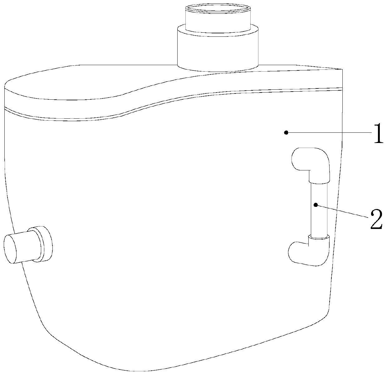
[0025] see Figure 1-Figure 6 , the present invention provides a domestic wastewater treatment and storage device, the structure of which includes a storage box 1 and a connecting pipe 2, the connecting pipe 2 is installed on the outer wall of the storage box 1, the connecting pipe 2 communicates with the storage box 1, and the The connecting pipeline 2 is set up in a U-shaped structure.

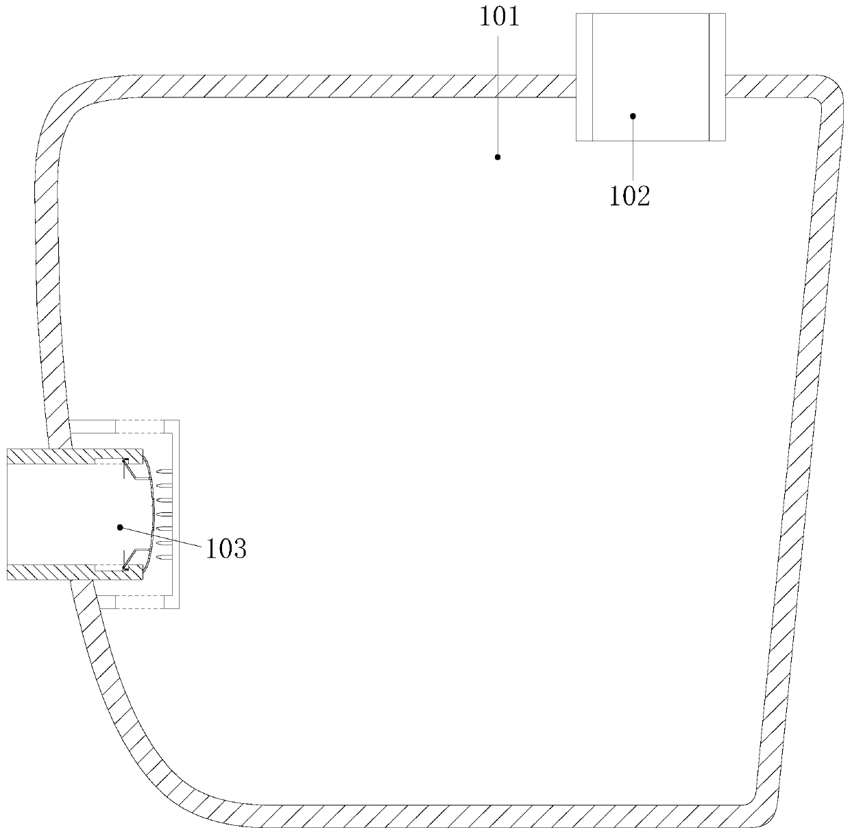
[0026] The storage box 1 is composed of a storage chamber 101, an inlet pipe 102, and an output pipe 103. The inlet pipe 102 is installed on the top of the storage box 1 and runs through it. The inlet pipe 102 communicates with the storage chamber 101. The aforementioned output tube 103 runs through the storage cavity 101 .

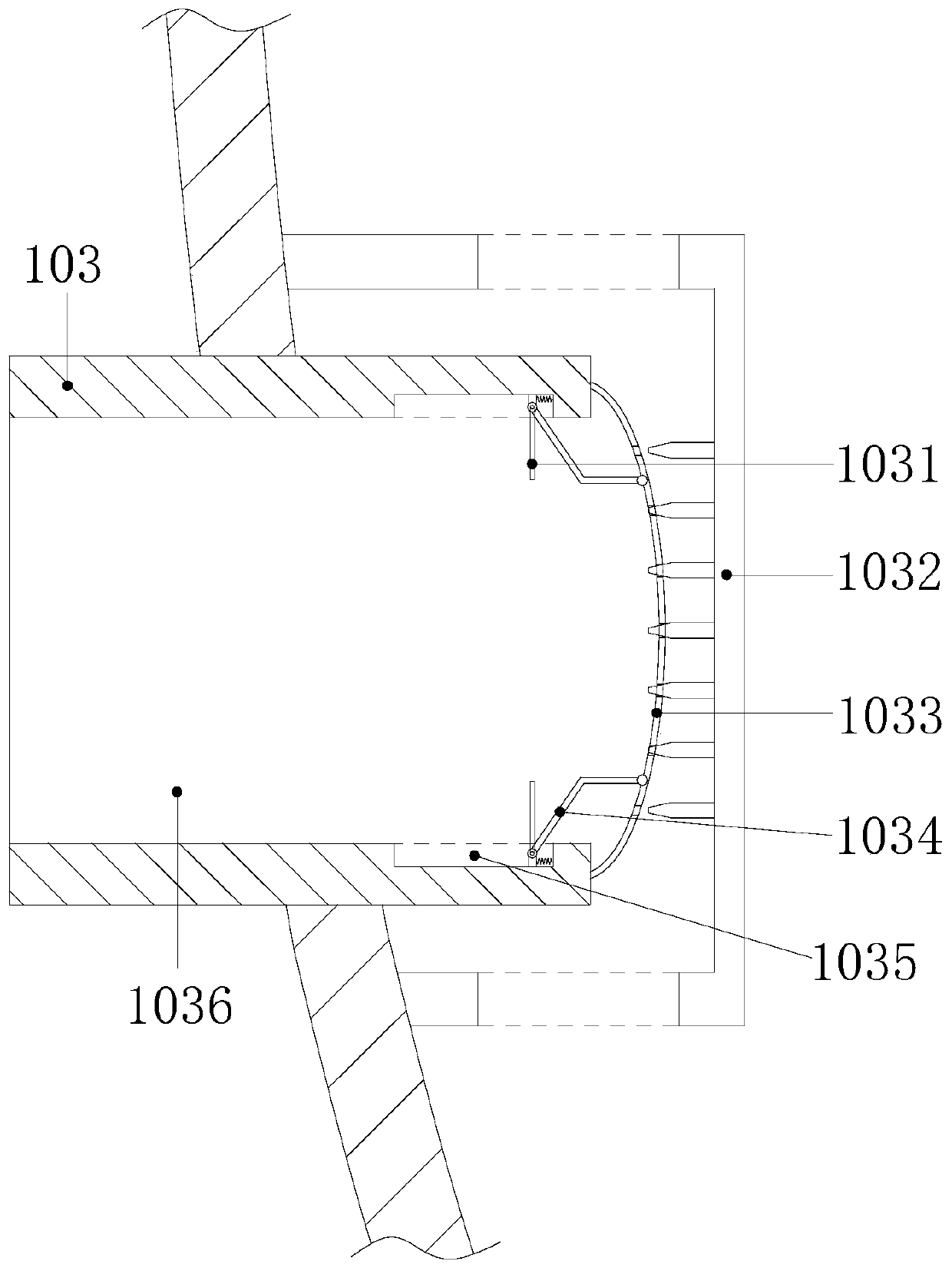
[0027] The output pipe 103 is composed of a drive plate 1031, a fixed cover 1032, an elastic filter plate 1033, a fixed rod 1034, a slide rail 1035, and an output channel 1036. The drive plate 1031 is provided with two symmetrical structures installed on the output In...


PUM


Abstract

The invention discloses a domestic wastewater treatment and storage device which structurally comprises a storage tank and a connecting pipeline, the connecting pipeline is arranged on the outer wallof the storage box, the connecting pipeline is communicated with the storage box, and the connecting pipeline is arranged in a u-shaped structure; the device has the beneficial effects that when wastewater flows out through an output channel, a driving plate is pushed to move in the same direction, an elastic filter plate is dragged by a fixing rod to move along with the driving plate, and a spring which is originally in a static state is stretched, so that the spring has a reverse-retraction force as a power source for resetting the driving plate, when wastewater outputting is stopped, the driving plate loses thrust, under the action of the traction force of shrinkage of the spring, the elastic filter plate rebounds, fixed pins penetrate through filter holes on the elastic filter plate, the fixed pins eject impurities clamped in the filter holes, and the filter holes are prevented from being blocked, so that the normal use of the elastic filter plate is guaranteed.

Description

technical field [0001] The invention relates to the field of domestic wastewater treatment, in particular to a domestic wastewater treatment and storage device. Background technique [0002] my country's water resources do not match the population ratio, and with the rapid economic development, people's water consumption in various aspects is increasing day by day, so the amount of domestic wastewater excreted increases accordingly. In fact, only a small part of the wastewater has been treated, and most of it They are all directly discharged into rivers without treatment, causing waste of water resources and polluting the environment at the same time. The current domestic wastewater treatment and storage devices have the following defects: [0003] People's domestic wastewater contains impurities. The treatment of domestic wastewater requires solid-liquid separation of wastewater to facilitate the next step of wastewater treatment. The traditional solid-liquid separation meth...

Claims


Application Information

Patent Timeline
Patent Type & Authority Applications(China)
IPC IPC(8): B01D29/05B01D29/62
Inventor 刘建生吴宝英刘培芬黄乞珠
Owner 山东同其数字技术有限公司
Why Eureka
Eureka Blog
Learn More