Power distribution cabinet inspection robot

A technology for inspection robots and power distribution cabinets, which is applied to manipulators, electrical components, switchgear, etc., can solve problems such as inconvenient use, inability to unlock, and inability to inspect power distribution cabinets, and achieve the effect of improving mobility

Inactive Publication Date: 2019-06-25
徐秀荣
View PDF9 Cites 11 Cited by
  • Summary
  • Abstract
  • Description
  • Claims
  • Application Information

AI Technical Summary

Problems solved by technology

[0002] Nowadays, power distribution cabinets are widely used in various fields. For public facilities, power distribution cabinets are usually placed in one place, and frequent inspections of power distribution cabinets are required to detect problems and safety hazards in power distribution cabinets in time. Now Design a power distribution cabinet inspection robot. There is a design of a power distribution cabinet inspection robot. For example, the patent application number CN201720688492.7 discloses a retractable power distribution cabinet door opening device, which can realize automatic switching The door of the power distribution cabinet, but it is inconvenient to use in practice and cannot be unlocked; for example, the patent number CN201620578129.5 discloses a power distribution cabinet installation device, which can realize the installation of the power distribution cabinet, but it cannot be installed on the power distribution cabinet. Inspection

Method used


Image

  • Power distribution cabinet inspection robot
  • Power distribution cabinet inspection robot
  • Power distribution cabinet inspection robot

Examples


Embodiment Construction

[0022] The technical solutions of the present invention will be further specifically described below through the embodiments and in conjunction with the accompanying drawings.

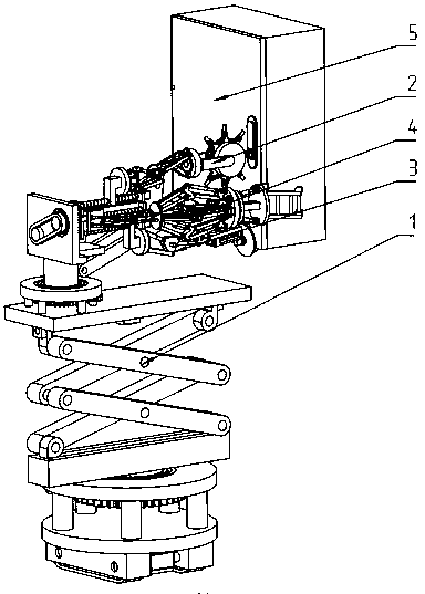
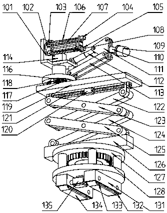
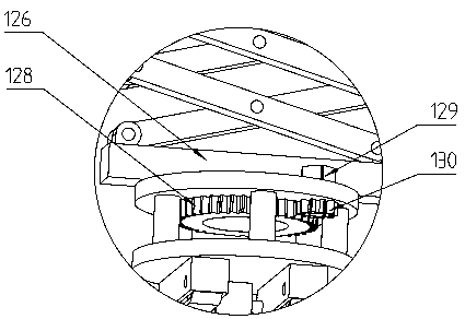
[0023] Example figure 1 , figure 2 , image 3 , Figure 4 , Figure 5 , Image 6 , Figure 7 , Figure 8 As shown, a power distribution cabinet inspection robot includes a body part 1, an unlocking part 2, a twisting part 3, and a door opening part 4. The body part 1 includes a rotating base 101, a rotating seat 102, a first stepping motor 103, The second stepper motor 104, the third stepper motor 105, T-shaped block, the first mounting plate, the first screw mandrel 106, the second screw mandrel 107, the third screw mandrel 108, camera 109, camera rod 110, double triangular plate 111, the first electric cylinder 112, the camera double rod 113, the fourth stepping motor 114, the main drive belt 115, the first gear 116, the fifth stepping motor 117, the second gear 118, the rotating bracket 119,...


PUM


Abstract

The invention provides a power distribution cabinet inspection robot. The robot comprises a machine body part, an unlocking part, a turning part and a door opening part, wherein the machine body partcomprises a rotary base, a rotating base, a first stepping motor, a second stepping motor, a third stepping motor, a T-shaped block, a first mounting plate, a first screw rod, a second screw rod, a third screw rod, a camera, a camera shooting rod, double triangular plates, a first electric actuator, camera shooting double rods, a fourth stepping motor, a main transmission belt, a first gear, a fifth stepping motor, a second gear and a rotating support, when the power distribution cabinet inspection robot is used, the machine body part moves to the vicinity of a power distribution cabinet needing inspection, the unlocking part is used for turning a lock of the power distribution cabinet, then a lock body ejects a turning block, the turning part is used for rotating the turning block by 90 degrees, at the moment, a cabinet door pops open, then the door opening part is used for opening the cabinet door, and the machine body part is used for carrying out scanning inspection on the interiorof the power distribution cabinet.

Description

technical field [0001] The invention relates to the technical field of power distribution cabinets, in particular to a power distribution cabinet inspection robot. Background technique [0002] Nowadays, power distribution cabinets are widely used in various fields. For public facilities, power distribution cabinets are usually placed in one place, and frequent inspections of power distribution cabinets are required to detect problems and safety hazards in power distribution cabinets in time. Now Design a power distribution cabinet inspection robot. There is a design of a power distribution cabinet inspection robot. For example, the patent application number CN201720688492.7 discloses a retractable power distribution cabinet door opening device, which can realize automatic switching The door of the power distribution cabinet, but it is inconvenient to use in practice and cannot be unlocked; for example, the patent number CN201620578129.5 discloses a power distribution cabine...

Claims


Application Information

Patent Timeline
Patent Type & Authority Applications(China)
IPC IPC(8): B25J11/00H02B3/00
Inventor 徐秀荣
Owner 徐秀荣
Why Eureka
Try Eureka