Deep trench excavation rapid forming machine and road culvert pipe refined construction method

A deep groove and fast technology, applied in the direction of road bottom, earth mover/shovel, construction, etc., can solve problems such as pipeline damage, collapse, blockage, low efficiency, and difficulty in ensuring the consistency of groove depth. , to achieve the effect of pipe laying operation

Pending Publication Date: 2019-06-25
ANHUI KAIYUAN HIGHWAY & BRIDGE +1
View PDF0 Cites 2 Cited by
  • Summary
  • Abstract
  • Description
  • Claims
  • Application Information

AI Technical Summary

Problems solved by technology

[0003] Although the construction cost of the above-mentioned concrete drainage pipes is low, the above-mentioned concrete pipes are prone to problems such as damage, collapse, and blockage
The leakage of urban municipal drainage network will cause damage to the urban environment and pollute urban groundwater, which has become the main source of groundwater pollution. Therefore, it is urgent to renovate the aging municipal drainage network in my country. With the advancement of polymer material technology, the pipes of the drainage system in recent decades mostly use polymer materials. The drainage pipes of the above polymer materials are not only light in weight, but also more convenient in the laying process. The above polymer drainage pipes are in In actual laying, in order to reduce the severe deformation of polymer material pipelines caused by ground subsidence or mechanical pressure, it is generally necessary to dig deep trenches to realize the arrangement of drainage pipelines and reduce the deformation of pipelines caused by ground mechanical pressure. In existing technologies, excavators are often used to dig trenches. Digging by excavators is not only inefficient, but also difficult to ensure the consistency of the depth of the trench. As a result, it is difficult to ensure the horizontal posture of the pipeline and the ground when the pipeline is arranged.

Method used


Image

  • Deep trench excavation rapid forming machine and road culvert pipe refined construction method
  • Deep trench excavation rapid forming machine and road culvert pipe refined construction method
  • Deep trench excavation rapid forming machine and road culvert pipe refined construction method

Examples


Embodiment Construction

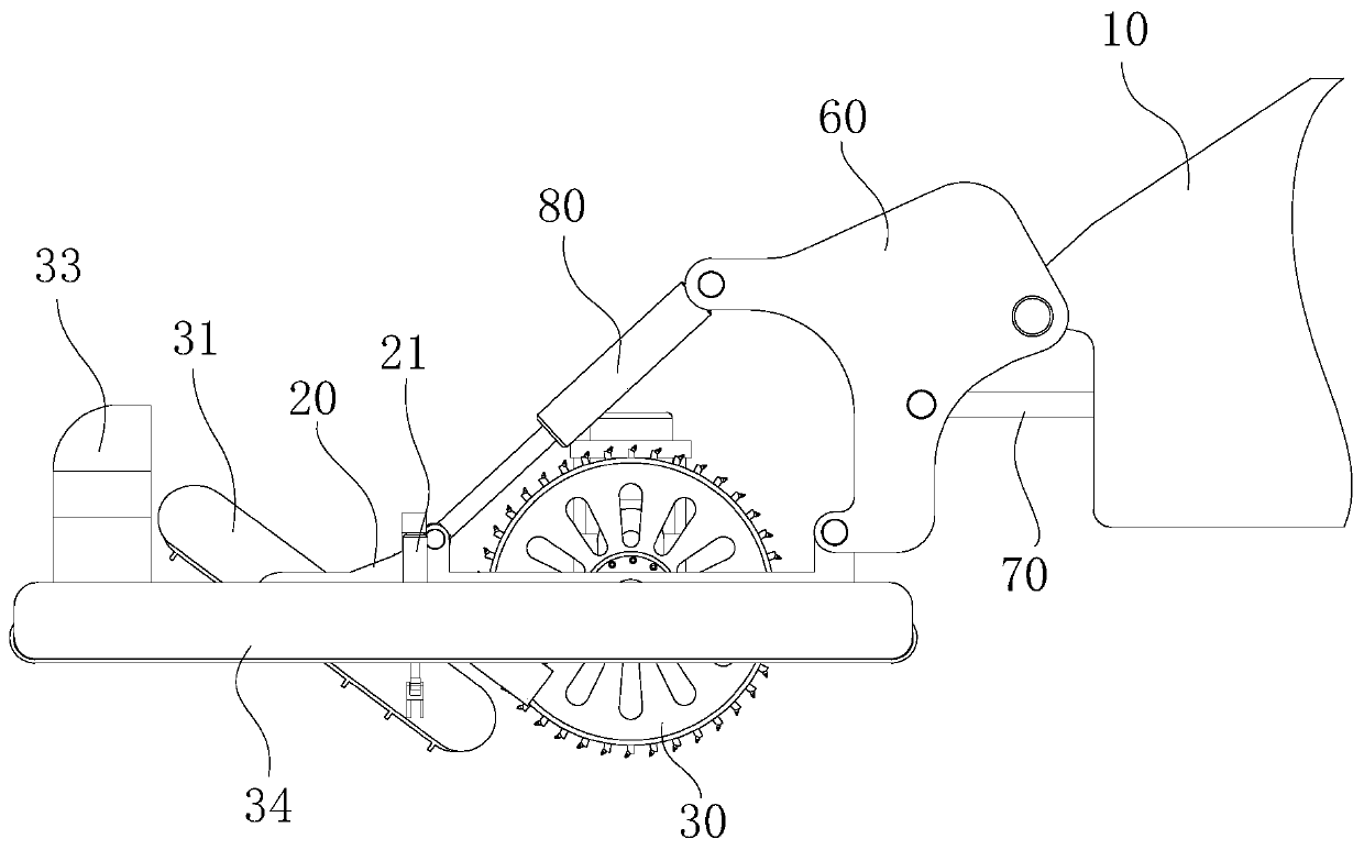
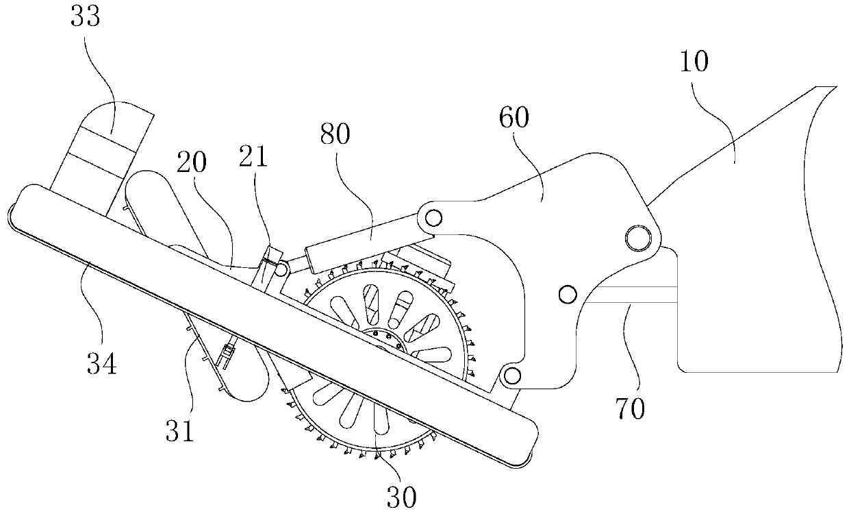
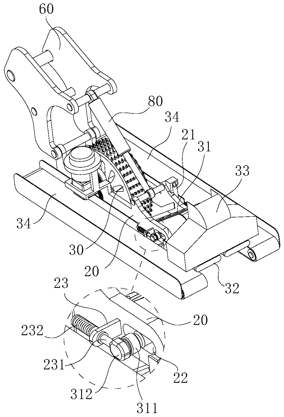
[0036] refer to Figure 1 to Figure 10 , the structural features of this deep trench excavation rapid prototyping machine are described in detail as follows:

[0037] The rapid prototyping machine for deep trench excavation includes a bracket arm 20 arranged on the mobile vehicle 10, and a milling wheel 30 is rotatably arranged on the bracket arm 20, and the milling wheel 30 has a wheel core and is connected with a driving mechanism. The driving mechanism drives the milling wheel 30 to rotate, and the side of the mobile vehicle 10 is also provided with a pipeline feeding mechanism 40, and the discharge port of the pipeline feeding mechanism 40 is provided with a pipeline laying mechanism 50, and the pipeline laying mechanism 50 the exit is horizontal and directed towards the rear end of the mobile vehicle 10;

[0038] combine figure 1 and figure 2 As shown, the mobile vehicle 10 supports the milling wheel 30 to move along the length direction of the base surface, and start...


PUM


Abstract

The invention relates to a deep trench excavation rapid forming machine comprising a bracket arm arranged on a moving vehicle. A milling wheel is arranged on the bracket arm in a rotating manner. A wheel core of the milling wheel is horizontal and is connected with a drive mechanism. The drive mechanism drives the milling wheel to rotate. A pipeline feeding mechanism is further arranged on the side of the moving vehicle. A pipeline laying mechanism is arranged at a discharge port of the pipeline feeding mechanism. An outlet of the pipeline laying mechanism is horizontal and points to the tailend of the moving vehicle. The moving vehicle carries the milling wheel to move along a construction base plane, the drive mechanism drives the milling wheel to rotate, and therefore excavation operation of a deep trench is achieved; and after deep trench excavation is completed, the pipeline feeding mechanism is started to lead and send pipelines into the pipeline laying mechanism and then the pipe laying operation is achieved.

Description

technical field [0001] The invention relates to the field of engineering construction, in particular to a rapid prototyping machine for excavating deep trenches and a refined construction method for road culverts. Background technique [0002] With the acceleration of urbanization, the requirements for the construction of urban drainage pipe network are increasing. In my country, the original urban drainage ditches are gradually replaced by concrete drainage pipes. Compared with traditional stone and brick ditches, concrete drainage pipes can not only greatly speed up the construction of drainage projects, but also reduce the cost of drainage projects. [0003] Although the construction cost of the above-mentioned concrete drainage pipe is low, the above-mentioned concrete pipe is prone to problems such as damage, collapse, and blockage. The leakage of urban municipal drainage pipe network will cause damage to the urban environment and pollute urban groundwater, which has b...

Claims


Application Information

Patent Timeline
IPC IPC(8): E02F5/08E01F5/00
Inventor 刘哲代良顺吴言安袁凌超李建响杨伐赵磊
Owner ANHUI KAIYUAN HIGHWAY & BRIDGE
Why Eureka
Try Eureka