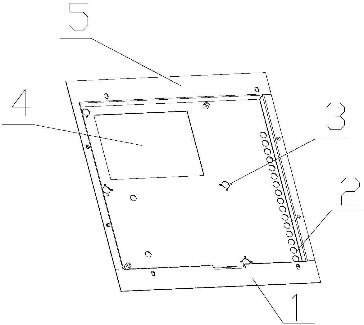
Drying machine box door

A technology for box doors and boxes, applied in dryers, drying rooms/containers, etc., can solve problems such as poor sealing, waste of energy, unfavorable heat storage, etc., and achieve high stability and good sealing effects

Inactive Publication Date: 2019-06-25
新昌县汉良苗木专业合作社
View PDF0 Cites 2 Cited by
  • Summary
  • Abstract
  • Description
  • Claims
  • Application Information

AI Technical Summary

Problems solved by technology

[0004] In view of this, the present invention aims to propose a dryer box door to solve the poor sealing of the existing dryer box door, which is not conducive to heat storage and wastes energy

Method used


Image

  • Drying machine box door

Examples


Embodiment Construction

[0020] It should be noted that, in the case of no conflict, the embodiments of the present invention and the features in the embodiments can be combined with each other.

[0021] In describing the present invention, it should be understood that the terms "center", "longitudinal", "transverse", "upper", "lower", "front", "rear", "left", "right", " The orientations or positional relationships indicated by "vertical", "horizontal", "top", "bottom", "inner" and "outer" are based on the orientations or positional relationships shown in the drawings, and are only for the convenience of describing the present invention and Simplified descriptions, rather than indicating or implying that the device or element referred to must have a particular orientation, be constructed and operate in a particular orientation, and thus should not be construed as limiting the invention. In addition, the terms "first", "second", etc. are used for descriptive purposes only, and should not be understood ...


PUM


Abstract

The invention provides a drying machine box door. The drying machine box door comprises a box door main body, wherein hinges are arranged on the outer side of the box door main body, and the box dooris fixed on the drying machine box body through hinges; a manhole is formed in the box door, and a transparent isolating device is arranged at the manhole; and a plurality of radiating holes are formed in one side of the box door, the outer side of the box door is provided with a heat dissipation hole cover corresponding to the heat dissipation holes, and the heat dissipation hole cover is used for closing or opening the heat dissipation holes. The drying machine box door has good sealing performance, and the function of the box door is executed effectively; and the manhole is arranged, so that the situation in a drying machine can be visually checked, the internal condition can be known in time, and meanwhile, the stability of the box door is high.

Description

technical field [0001] The invention belongs to the technical field of drying equipment, and in particular relates to a drying machine box door. Background technique [0002] The dryer has several modes such as belt drying, drum drying, box drying, and tower drying; the heat source includes coal, electricity, gas, etc.; the drying process of materials has hot air flow type and radiation type, etc. , hot air drum drying is that the hot air flow moves forward from the tail, fully contacts with the material, and makes full use of the heat transfer through heat conduction, convection, and radiation; the heat energy is directly transferred to the material, so that the moisture of the material is continuously evaporated in the cylinder, and the material is fed into the cylinder. The air-introduction device at the outlet draws out a large amount of water and wet air to prevent secondary pollution caused by dust discharge; through internal spiral stirring, sweeping and lifting, the ...

Claims


Application Information

Patent Timeline
Patent Type & Authority Applications(China)
IPC IPC(8): F26B25/12
Inventor 朱汉文
Owner 新昌县汉良苗木专业合作社
Why Eureka
Try Eureka