Electrode for potential detection of electromagnetic flowmeter

An electromagnetic flowmeter and potential detection technology, which is applied in the application of electromagnetic flowmeter to detect fluid flow, volume/mass flow generated by electromagnetic effects, liquid level indicator for physical variable measurement, etc., can solve the peeling of precious metal materials and corrosion of measuring tubes , Measuring tube to apply impact, etc.

Active Publication Date: 2019-06-25
YAMATAKE HONEYWELL CO LTD
View PDF9 Cites 3 Cited by
  • Summary
  • Abstract
  • Description
  • Claims
  • Application Information

AI Technical Summary

Problems solved by technology

[0003] However, when abrasive objects are mixed into the fluid flowing through the measuring tube, the noble metal material covering the electrodes may be peeled off.
In addition, the noble metal material covering the electrodes may be peeled off due to impacts applied to the measuring tube, corrosion of the measuring tube, defects during manufacturing, etc.

Method used


Image

  • Electrode for potential detection of electromagnetic flowmeter
  • Electrode for potential detection of electromagnetic flowmeter
  • Electrode for potential detection of electromagnetic flowmeter

Examples


no. 1 Embodiment approach

[0034] Below, refer to Figure 1 ~ Figure 5 An embodiment of the electrode for potential detection of the electromagnetic flowmeter according to the present invention will be described in detail.

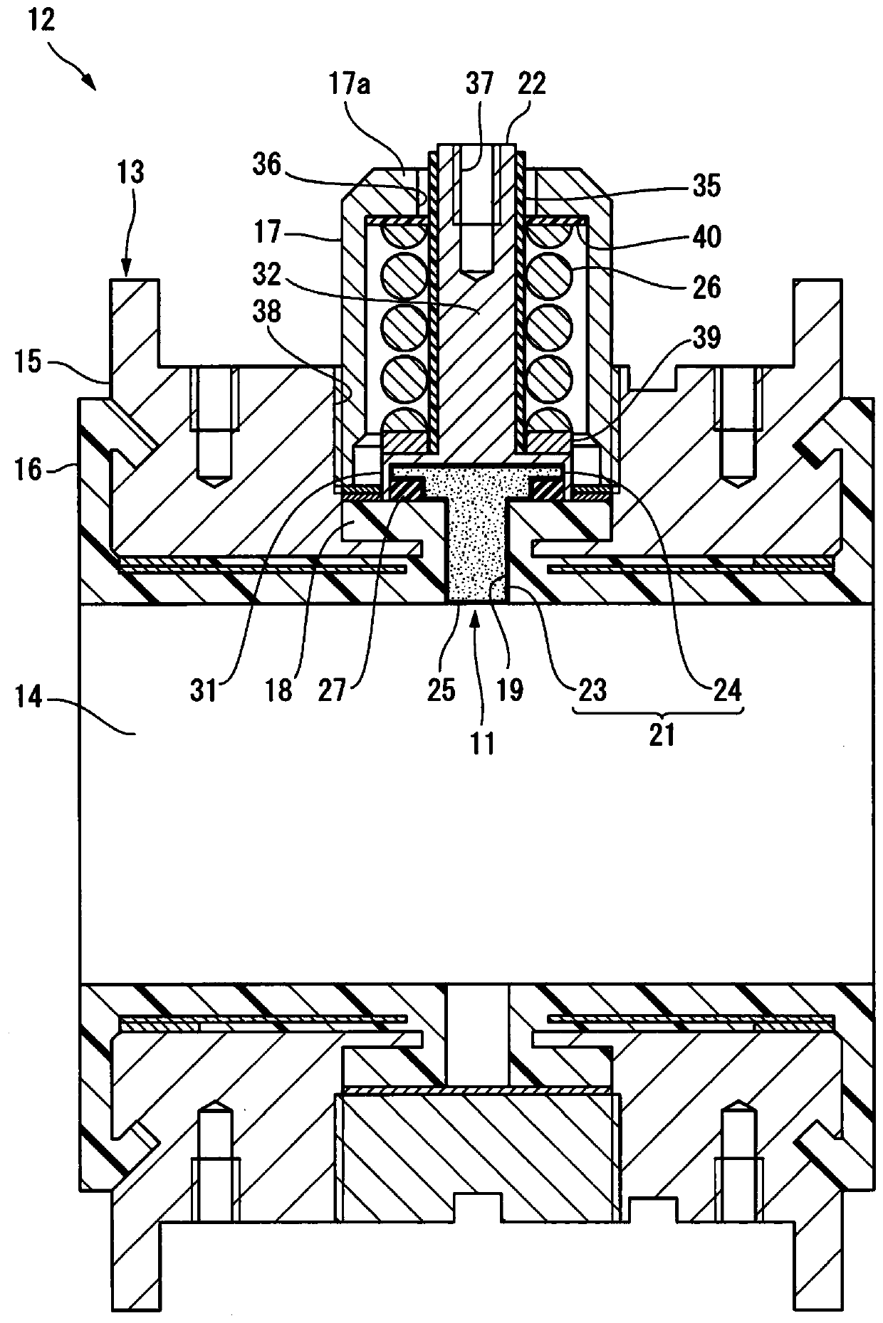
[0035] figure 1 The illustrated electrode 11 for potential detection (hereinafter, simply referred to as electrode 11) is attached to the measuring tube 13 of the electromagnetic flowmeter 12 from the outside of the fluid passage 14.

[0036] The measurement tube 13 includes a main body 15, an inner liner 16 provided on the inner surface of the main body 15, a bottomed cylindrical electrode cap 17 that accommodates the electrode 11, and the like. The electrode mounting seat 18 is integrally provided to the inner liner 16. The electrode mounting seat 18 is provided with an electrode insertion hole 19 for inserting the electrode 11.

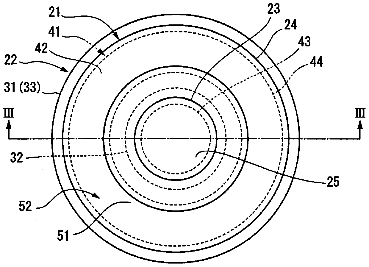
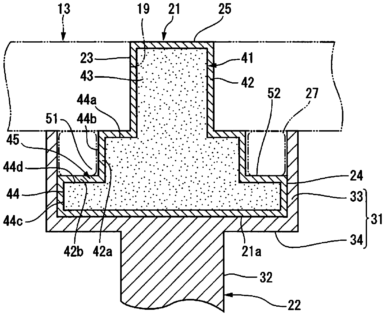
[0037] The electrode 11 of the present embodiment includes a main body 21 inserted into the electrode insertion hole 19 of the inner liner 16 and a terminal ...

no. 2 Embodiment approach

[0053] The electrode for potential detection of the present invention can be as Image 6 as well as Figure 7 Structure as shown. in Image 6 as well as Figure 7 In, for and Figure 1 ~ Figure 5 The same or equivalent members of the described members are denoted by the same reference numerals, and detailed descriptions are appropriately omitted.

[0054] Image 6 as well as Figure 7 The shown potential detection electrode 61 is composed of a main body 21 and a terminal 22. The main body 21 has a large-diameter disk-shaped portion 24 without a step on the outer periphery. The terminal 22 is provided with the main body 21 The outer peripheral surface of the fitting cylinder 33. The large-diameter portion 24 of the main body portion 21 is formed such that the outer diameter is constant over the entire area in the axial direction.

[0055] The cylindrical body 33 of this embodiment has a first inner peripheral surface 33b extending in the axial direction from the inner peripheral ed...


PUM


Abstract

The present invention provides an electrode for potential detection of an electromagnetic flowmeter, which has high conduction reliability despite having an annular groove covered by a conductor. Theelectrode includes a main body portion (21) including a liquid-contact portion (25) exposed into a measurement tube (13) and formed by covering a base material (41) with a conductor (42); a terminal portion (22) electrically connected to the conductor (42). The main body portion (21) includes a small diameter portion (23) having a cylindrical shape and a large diameter portion (24) having a disc shape extending outward from the small diameter portion (23) in a radial direction. The terminal portion (22) includes an electrically conductive body (31) having a cylindrical body (33) that accommodates the large diameter portion (24) fitted therein and a shaft portion (32) extending from the electrically conductive body (31) in a direction opposite to the main body portion (21). The large diameter portion (24) is provided on an outer peripheral portion thereof with an annular recessed portion (51) that defines an annular groove (52) between the large diameter portion (24) and the cylindricalbody (33).

Description

Technical field [0001] The present invention relates to a potential detection electrode including an electromagnetic flowmeter in which a main body of a liquid contact part is covered with a conductive material. Background technique [0002] As a conventional electromagnetic flowmeter, there is a configuration in which the electromotive force generated in the fluid flowing in the measuring tube is taken out by the electrode for potential detection. The material for forming the potential detection electrode is usually stainless steel, but various materials are used depending on the corrosiveness of the detection object. As electrode materials with high corrosion resistance, noble metal materials such as platinum disclosed in Patent Document 1 are frequently used. The material strength of noble metal materials is low, so there are disadvantages such as shapes that cannot be manufactured. In order to solve this problem, a non-noble metal material is used as the base metal to form ...

Claims


Application Information

Patent Timeline
Patent Type & Authority Applications(China)
IPC IPC(8): G01F1/58
CPCG01F1/584G01N27/07G01F1/588G01F23/24G01N27/06
Inventor 木村宏治
Owner YAMATAKE HONEYWELL CO LTD
Why Eureka
Try Eureka