
Antenna equipment for communication

A technology of antenna equipment and central axis, which is applied in the direction of antenna, antenna coupling, antenna parts, etc., can solve the problems of no anti-interference, inability to adjust, and influence on signal reception, so as to improve signal reception efficiency, facilitate reception, and signal accept the effect of stabilization

Inactive Publication Date: 2019-06-25
滑迪
View PDF1 Cites 0 Cited by
  • Summary
  • Abstract
  • Description
  • Claims
  • Application Information

AI Technical Summary

Problems solved by technology

[0003] The mobile communication self-switching beam antenna system and its antenna in the above-mentioned patent have the following disadvantages: only multiple groups of antenna beams are used to enhance signal reception, the cost is high, there is no anti-interference, and at the same time it cannot be adjusted, which will affect signal reception

Method used


Image

  • Antenna equipment for communication
  • Antenna equipment for communication
  • Antenna equipment for communication

Examples


Embodiment Construction

[0020] The following will clearly and completely describe the technical solutions in the embodiments of the present invention with reference to the accompanying drawings in the embodiments of the present invention. Obviously, the described embodiments are only some, not all, embodiments of the present invention.

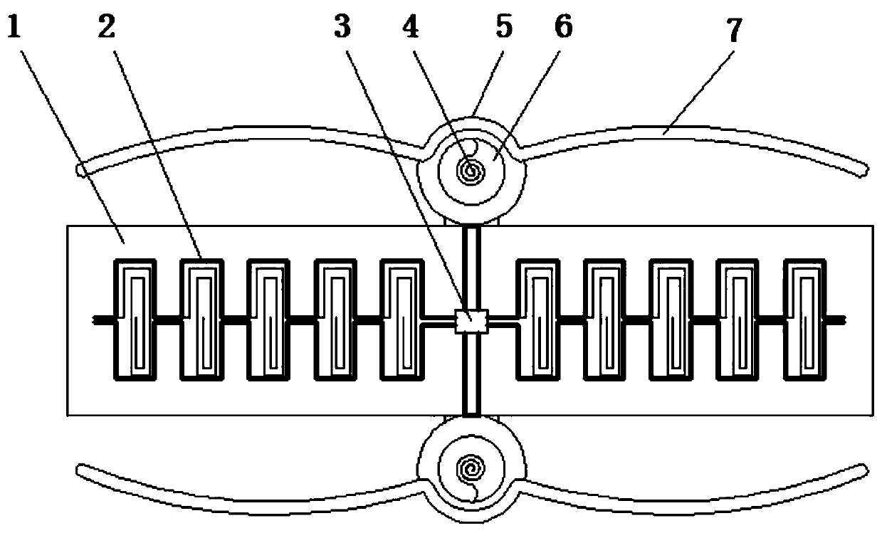
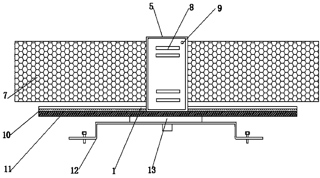
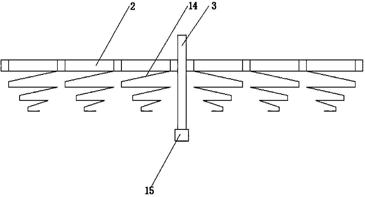
[0021] refer to Figure 1-3 , a communication antenna device, comprising a mounting frame 12, a through hole is opened at the central axis of the outer wall of the top of the mounting frame 12, and a base 13 is welded on the inner wall of the through hole, and an abutment 1 is welded at the central axis of the outer wall of the top of the base 13, and the base The platform 1 includes a base plate 11 and a waterproof board 10. The bottom outer wall of the waterproof board 10 is bonded to the top outer wall of the base plate 11. A second through hole is opened at the central axis of the top outer wall of the abutment 1, and a rotating seat is welded on the inner wall of...


PUM


Abstract

The invention discloses a piece of antenna equipment for communication, including a mounting frame. A through hole is arranged at the central axis of the top outer wall of the mounting frame, and a base is welded to the inner wall of the through hole. A pedestal is welded at the central axis of the top outer wall of the base, and the pedestal includes a base plate and a waterproof plate. The bottom outer wall of the waterproof plate is bonded to the top outer wall of the base plate. A second through hole is arranged at the central axis of the top outer wall of the pedestal, and a rotating seatis welded to the inner wall of the second through hole. The bottom inner wall of the rotating seat is connected with a main support through a bearing, and side-wing convoluted wire frames are weldedto the tops of the outer walls of the two sides of the main support. Through the cooperation between spiral vertical auxiliary coils and side-wing convoluted coils, the signal receiving efficiency canbe improved. The antenna equipment replaces multiple antenna beams, and the cost is reduced. An anti-interference screen plate and a signal enhancement bar can shield the interference of different frequency signals from outside, and can enhance the signal at a fixed frequency to make the signal received stably. The rotating seat can be adjusted in different directions to facilitate signal reception.

Description

technical field [0001] The present invention relates to the technical field of communication equipment, in particular to an antenna equipment for communication. Background technique [0002] Communication antenna is an important part of satellite communication equipment. Users can comprehensively choose according to the use environment, bearing mode, geographical location, main business and budget of the communication antenna. For multi-band, for example, two-band communication Most of the existing technologies use two circularly polarized antennas to realize communication in different frequency bands by controlling the structural size and dielectric constant of each antenna. With the rapid development of mobile communication technology and the sharp increase in mobile communication traffic, mobile communication The coverage area of ​​the network is constantly expanding and improving. As one of the key components of the mobile communication system, the base station antenna b...

Claims


Application Information

Patent Timeline
Patent Type & Authority Applications(China)
IPC IPC(8): H01Q1/12H01Q1/52H01Q3/04H01Q1/00
Inventor 滑迪
Owner 滑迪
Learn More