
Low-noise primary amplification circuit suitable for transmitting-receiving combined transducer and noise decomposition method

A primary amplification, combined transceiver technology, applied in the direction of improving amplifiers to reduce noise effects, improving amplifiers to improve efficiency, and improving amplifiers to reduce the harmful effects of internal resistance, which can solve problems such as reducing circuit receiving efficiency and improve signal Reception efficiency, effect of reducing circuit noise

Pending Publication Date: 2020-02-07
杭州瑞利海洋装备有限公司
View PDF0 Cites 0 Cited by
  • Summary
  • Abstract
  • Description
  • Claims
  • Application Information

AI Technical Summary

Problems solved by technology

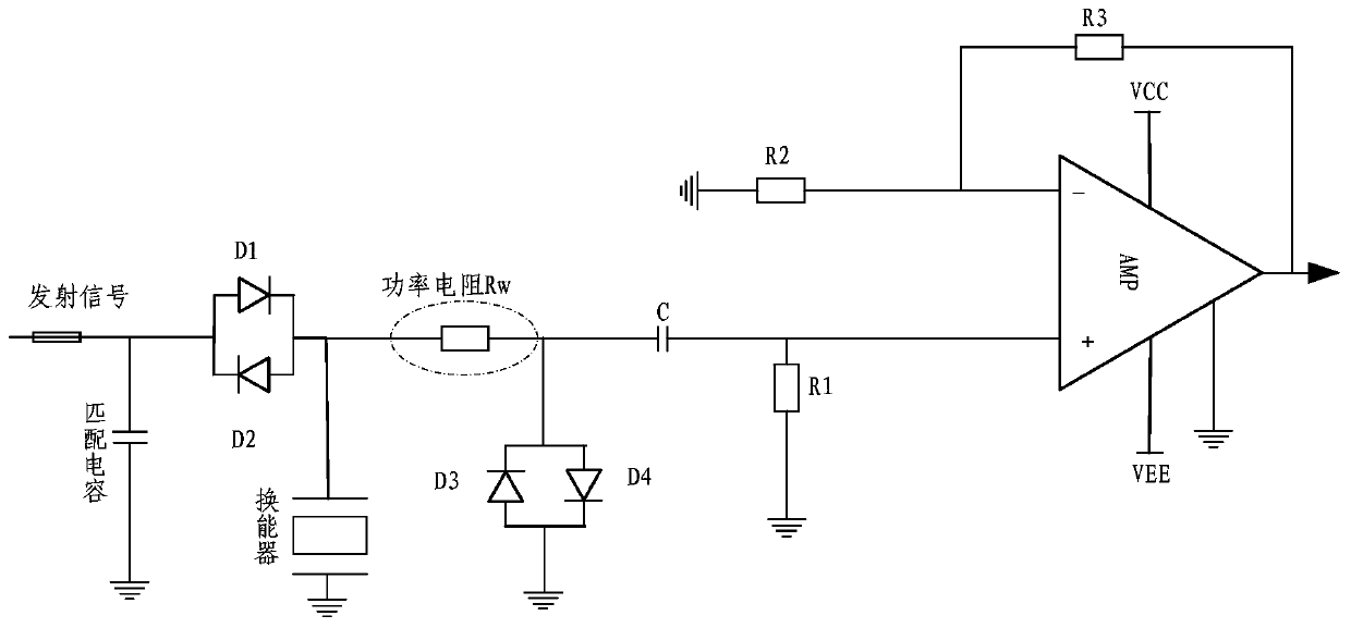
The disadvantage is that in order to reduce the influence of the power resistor on the emission efficiency, the resistance value is required to be much larger than the transducer impedance. When the transducer impedance is large, the thermal noise of the power resistor is much larger than other noises, and it becomes the main noise source of the primary amplifier circuit, and the The resistor and the resistor R in the RC filter circuit at the input of the amplifier circuit form a voltage divider circuit, which reduces the receiving efficiency of the circuit and becomes an important factor limiting the operating distance of sonar equipment

Method used


Image

  • Low-noise primary amplification circuit suitable for transmitting-receiving combined transducer and noise decomposition method
  • Low-noise primary amplification circuit suitable for transmitting-receiving combined transducer and noise decomposition method
  • Low-noise primary amplification circuit suitable for transmitting-receiving combined transducer and noise decomposition method

Examples


Embodiment

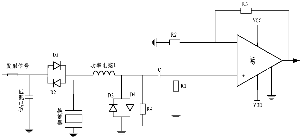
[0018] Embodiment: As shown in the accompanying drawings, this low-noise primary amplifying circuit suitable for transceiving and displacing transducers mainly includes a transceiving conversion module, a filter module, and an operational amplifier circuit. The transceiving conversion module is provided with protective diode pairs D1, D2, D3, D4, and resistor R4 and power inductor L. The filter module includes resistor R1, capacitor C, and power inductor to form a bandpass filter. The operational amplifier circuit is composed of low voltage, current noise operational amplifier and resistors R2 and R3.

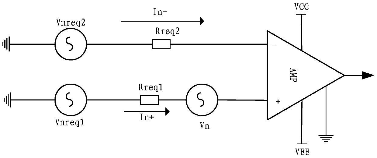
[0019] The equivalent input noise model of the low-noise primary amplifier circuit decomposes the circuit noise into five parts and gives the corresponding calculation method, which mainly includes the following contents:

[0020] 1) Amplify the chip voltage noise Vn;

[0021] 2) Amplify the flow noise Vireq1 generated by the current noise In of the chip flowing through the equ...


PUM


Abstract

The invention discloses a low-noise primary amplification circuit suitable for a transmitting-receiving combined transducer and a noise decomposition method. The circuit mainly comprises a transceiving conversion module, a filtering module and an operational amplification circuit. the transceiving conversion module is provided with protection diode pairs D1, D2, D3 and D4, a resistor R4 and a power inductor L; the filtering module comprises a resistor R1 and a capacitor C, band-pass filtering is formed by the filtering module and the power inductor, and the operational amplification circuit isformed by a low-voltage and current noise operational amplifier, a resistor R2 and a resistor R3. The power inductor is used for replacing a power resistor of the receiving-transmitting conversion module, RC filtering parameters of the input end of the amplifying circuit are adjusted and optimized, and therefore influences of the power resistor in an original circuit on noise of the amplifying circuit and signal receiving efficiency are eliminated; the circuit and method can be used for low-noise amplification and circuit noise magnitude evaluation of active sonar echo signals; the signal receiving efficiency is improved; a noise calculation model is established, the correctness of circuit design is verified, and the design of circuits of the same type can be guided.

Description

technical field [0001] The invention relates to the field of active sonar signal receiving circuits, in particular to a low-noise primary amplifying circuit and a noise decomposition method suitable for transceiving and displacing transducers. Background technique [0002] It can be seen from the Frith formula that the cascaded amplifier circuits have different influences on the noise at each stage, and the higher the front stage, the greater the influence. When the amplification factor of the primary amplifying circuit is large enough, the total noise of the system depends on the noise of the primary amplifying circuit. Therefore, the low-noise design of the primary amplifier circuit is very important. [0003] When the transmitter and receiver share the same transducer array, a transceiver conversion module must be used to protect the receiver from high-power signal damage during transmission and to receive echoes normally during reception. At present, the widely used tr...

Claims


Application Information

Patent Timeline
Patent Type & Authority Applications(China)
IPC IPC(8): H03F1/26H03F1/02H03F1/08G01S7/52
CPCG01S7/52H03F1/02H03F1/08H03F1/26
Inventor 彭阳明杭亮徐春秋
Owner 杭州瑞利海洋装备有限公司
Learn More