
Electric power stringing unmanned aerial vehicle

A drone and electric power technology, applied in the field of drones, can solve the problems of poor drone operation, external battery drop, weak signal, etc., to achieve the effect of convenient and fast adjustment, guaranteeing protection performance, and ensuring stability

Active Publication Date: 2022-05-13
BEIJING NORTH STAR DIGITAL REMOTE SENSING TECH CO LTD
View PDF12 Cites 0 Cited by
  • Summary
  • Abstract
  • Description
  • Claims
  • Application Information

AI Technical Summary

Problems solved by technology

In the prior art, in order to facilitate the wiring between different mountains when wiring in mountainous areas, drones are often used to pull the wires, so the signal reception of drones is very important, but the existing drones are responsible for signal The receiving antenna is often fixedly installed on the top of the UAV, and the signal will be weak during the UAV pulling the wire, resulting in poor operation of the UAV. The flight distance of the UAV is very large, and a long wire needs to be pulled to move during the pulling process. Therefore, this type of UAV often needs an external battery for assistance. In the prior art, the external battery is bound by a strap. The quality of the strap on the top or bottom of the drone determines the stability of the external battery, which makes it possible for the external battery to fall

Method used


Image

  • Electric power stringing unmanned aerial vehicle
  • Electric power stringing unmanned aerial vehicle
  • Electric power stringing unmanned aerial vehicle

Examples


Embodiment 1

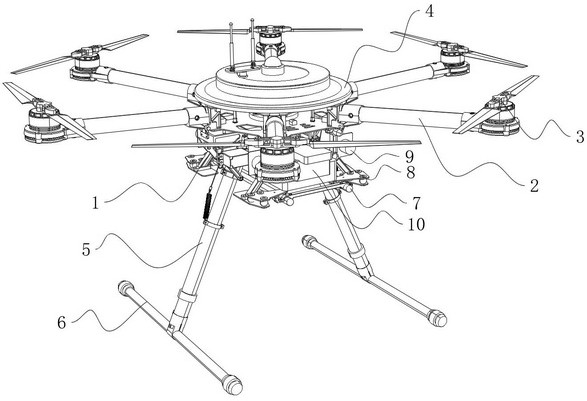
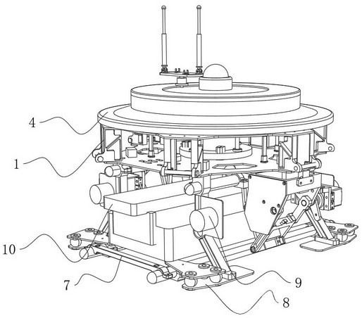
[0037] Such as Figure 1-7 As shown, it is the first embodiment of the present invention, which provides a kind of electric power wire UAV, including a body 1, and six wings 2 are evenly arranged on the side of the body 1, and the wings 2 are far away from the body 1. A propeller 3 is installed at one end, a top cover plate 4 is fixedly installed on the top of the body 1, an outrigger 5 is installed on the bottom of the body 1, and an end of the outrigger 5 far away from the body 1 is fixedly installed with a vertically arranged The bottom of the body 1 is also provided with a support frame 7, the support frame 7 is located between the two legs 5, the bottom of the support frame 7 is installed on the bottom of the body 1 through the lifting frame 8, and the bottom of the body 1 is also installed. A clamping assembly 10 is arranged directly above the supporting frame 7 on the adjusting motor 9 that controls the lifting of the lifting frame 8 , and the clamping assembly 10 is fi...

Embodiment 2

[0044] This embodiment is based on the previous one.

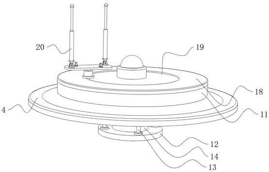
[0045] Such as Figure 3-8 As shown, the antenna assembly 20 includes a rotating plate 21, the rotating plate 21 is fixedly installed on the top end of the output shaft of the rotating motor 179, the top end of the rotating plate 21 is fixedly installed with a mounting base 22, and the top end of the mounting base 22 is fixedly installed There is an antenna sleeve 23, and one end of the antenna sleeve 23 is telescopically provided with an antenna body 24. The top end of the antenna body 24 is fixedly equipped with a cap 25. In order to enable the antenna body 24 to be folded, the mounting seat 22 in this embodiment Set the folding type, when the antenna body 24 does not need to be used, the antenna body 24 can be received in the antenna sleeve 23, and then the antenna sleeve 23 is folded along the rotation point of the mount 22, in order to make the folded antenna sleeve 23 can fit on the rotating plate 21 more stably, an...

Embodiment 3

[0050] This embodiment is based on the previous two embodiments.

[0051] Such as Figure 1-14As shown, in order to make the clamping assembly 10 automatically tighten the items on the support frame 7 when the elevating frame 8 and the electric support frame 7 rise, in this embodiment, the clamping assembly 10 includes a mounting plate 101, and the mounting plate 101 is connected with the support Frame 7 is parallel, and its installation plate 101 is arranged along the length direction of support frame 7, and the top center of installation plate 101 is fixedly installed with installation sleeve 102, and installation plate 101 is fixedly installed on the bottom center of body 1 by installation sleeve 102, and installation plate The bottom of 101 is fixedly installed with fixed blocks 103 at both ends arranged along its length direction, and two symmetrically arranged guide rods 104 are fixedly installed between the two fixed blocks 103, and a symmetrically arranged moving block...


PUM


Abstract

The invention belongs to the technical field of unmanned aerial vehicles, and particularly relates to an electric power stringing unmanned aerial vehicle which comprises a vehicle body, wings, propellers, a top cover plate, supporting legs and supporting foot rods, a supporting frame is arranged at the bottom of the vehicle body, the bottom of the supporting frame is installed at the bottom of the vehicle body through a lifting frame, an adjusting motor is further installed at the bottom of the vehicle body, and a clamping assembly is arranged over the supporting frame. The antenna assembly can rotate through the rotating assembly, so that the antenna assembly keeps rotating all the time during use, the signal receiving efficiency of the antenna assembly is improved, the arranged rotating motor can enable the antenna assembly to rotate, the signal receiving efficiency of the antenna assembly is further improved, and the antenna assembly is more convenient to use. When the antenna body is not used, the antenna body can be retracted into the antenna sleeve and folded, the clamping assembly can achieve automatic clamping when the supporting frame drives an object to ascend, the stability of the object brought up by the machine body is guaranteed, when the supporting frame descends, the clamping assembly can also be automatically loosened, and adjustment is convenient and fast.

Description

technical field [0001] The invention belongs to the technical field of unmanned aerial vehicles, and in particular relates to an electric wire unmanned aerial vehicle. Background technique [0002] Unmanned aircraft, referred to as "UAV", is an unmanned aircraft that is controlled by radio remote control equipment and its own program control device, or is completely or intermittently operated autonomously by an on-board computer. According to the application field, UAV can be divided into military and civilian. Applications in aerial photography, agriculture, plant protection, micro selfies, express transportation, disaster relief, wildlife observation, infectious disease monitoring, surveying and mapping, news reports, power inspections, disaster relief, film and television shooting, and romance creation have greatly expanded For the use of drones themselves, developed countries are also actively expanding industry applications and developing drone technology. In the prio...

Claims


Application Information

Patent Timeline
Patent Type & Authority Applications(China)
IPC IPC(8): B64D47/00H01Q1/28H01Q1/08H01Q1/10H01Q3/08
CPCB64D47/00H01Q1/285H01Q3/08H01Q1/10H01Q1/084B64U30/20B64U10/10B64U2101/00
Inventor 杨乐乐陈文强
Owner BEIJING NORTH STAR DIGITAL REMOTE SENSING TECH CO LTD
Learn More