Buckle base structure in plastic mold tensioning mechanism

A technology of plastic molds and templates, applied in the field of buckle base structure, can solve the problems such as excessive pulling force, deformation and breakage of the buckle base, and achieve the effect of avoiding deformation or breakage

Active Publication Date: 2019-06-28
佛山市天驭塑料制品有限公司
View PDF10 Cites 2 Cited by
  • Summary
  • Abstract
  • Description
  • Claims
  • Application Information

AI Technical Summary

Problems solved by technology

[0005] Aiming at the deficiencies in the prior art, the purpose of the present invention is to provide a buckle base structure in the tensioning mechanism of a plastic mold, so as to solve the problem that the buckle base in the tensioning mechanism of the prior art is in use due to the impact of the buckle base on the mold. The upper and lower templates are pre-tightened to lock the mold and release the mold. When the buckle base is installed at the same level with a large deviation, only one side of the buckle base will be stressed. The unbalanced force will cause the buckle base to break, and because the buckle base After installation, the upper and lower mold cores are horizontally controlled to separate and take out the plastic parts. The separation force is usually a large power source such as an air pump or hydraulic pressure. When the set value exceeds the stroke, the base will be buckled. Defects that bear excessive pulling force, resulting in deformation or fracture

Method used


Image

  • Buckle base structure in plastic mold tensioning mechanism
  • Buckle base structure in plastic mold tensioning mechanism
  • Buckle base structure in plastic mold tensioning mechanism

Examples


Embodiment Construction

[0026]In order to make the technical means, creative features, goals and effects achieved by the present invention easy to understand, the present invention will be further described below in conjunction with specific embodiments.

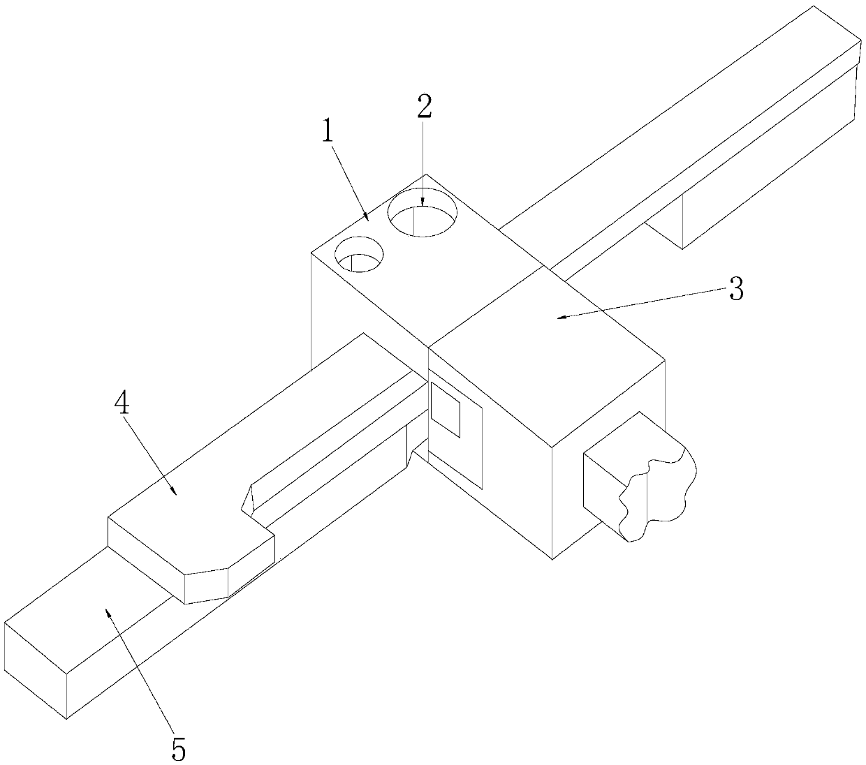
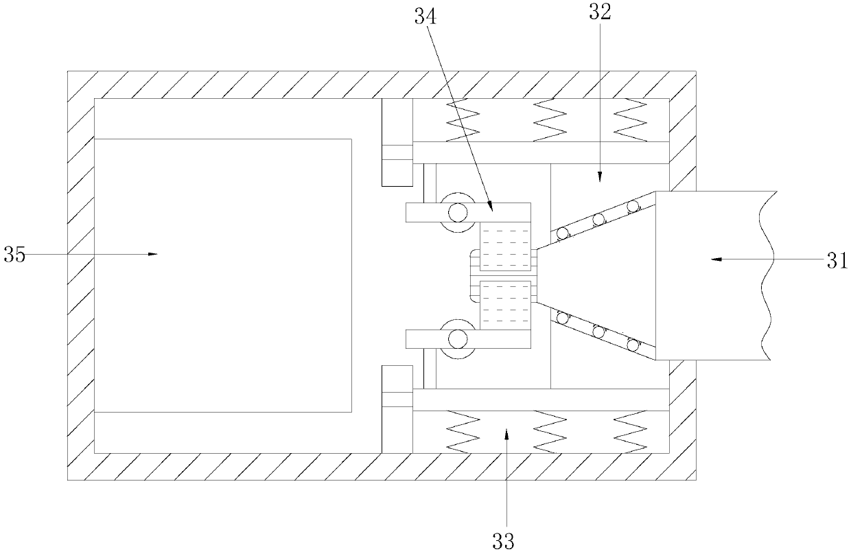
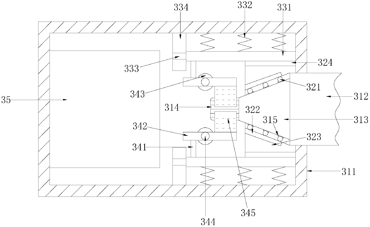
[0027] Such as Figure 1-Figure 5 As shown, the present invention provides a technical scheme of the buckle base structure in the tensioning mechanism of a plastic mold:

[0028] A buckle base structure in a tensioning mechanism of a plastic mold, the structure of which includes a device locking block 1, a threaded connection block 2, a plugging extrusion alignment force unloading device 3, an upper template tensioning block 4, and a lower template tensioning block 5 The threaded connection block 2 is provided with two penetratingly installed inside the device locking block 1 and is an integrated structure, the right side surface of the device locking block 1 is in contact with the left side surface of the plugging extrusion alignment force unloadi...


PUM


Abstract

The invention discloses a buckle base structure in a plastic mold tensioning mechanism. The structure comprises a device locking block, two threaded connecting blocks, a plug extrusion alignment forceremoving device, an upper mold plate tensioning block and a lower mold plate tensioning block, wherein the two threaded connecting blocks penetrate through and are integrated with the inside the device locking block; and the right side surface of the device locking block is connected with the left side surface of the plug extrusion alignment force removing device. According to the structure, an alignment rod can be installed and inserted into the buckle base to be installed, and an internal bonding rubber ring is matched with an insertion rubber block to stabilize so as to ensure that the installed buckle base is on the same horizontal plane and the buckling of the buckle base is not broken due to unbalance stress; and when the buckle base exceeds the stroke, internal high-pressure air can be squeezed by squeezing and impacting the rubber block to push the force removing plate to remove the pulling force exceeding the stroke, so that deformation or breakage of the buckle base is avoided.

Description

technical field [0001] The invention relates to the field of plastic molds, more precisely, it relates to a buckle base structure in a tensioning mechanism of a plastic mold. Background technique [0002] Plastic is to inject some hot-dissolved chemical components into the core of the mold to solidify and plasticize into a specified model through cooling water channels. The buckle base is to connect the upper mold core plate and the lower mold core plate of the mold to transmit huge pulling force. , to prevent stripping of the connection fixation. However, the present buckle base structure in this plastic mold tensioning mechanism has the following disadvantages: [0003] 1. When the buckle base structure in the tensioning mechanism is in use, because the buckle base pre-tightens the upper and lower templates of the mould, when the buckle base is installed at the same level, the deviation is large, resulting in only one side of the buckle The base is stressed, and the unba...

Claims


Application Information

Patent Timeline
Patent Type & Authority Applications(China)
IPC IPC(8): B29C45/64B29C33/20
Inventor 孙助奎谢彬彬高金萍
Owner 佛山市天驭塑料制品有限公司
Why Eureka
Try Eureka