
Novel liquid storage and filling cover belt oil-blocking ventilation mechanism assembly for automobile

A new type of liquid storage irrigation technology, which is applied to vehicle components, reservoir layout, brake components, etc., can solve problems such as difficult to withstand rapid impact, brake fluid leakage, damage, etc., and achieve reliable and stable performance and long service life , good effect

Pending Publication Date: 2019-06-28
ZHEJIANG ASIA PACIFIC MECHANICAL & ELECTRONICS
View PDF0 Cites 0 Cited by
  • Summary
  • Abstract
  • Description
  • Claims
  • Application Information

AI Technical Summary

Problems solved by technology

[0002] In the traditional automobile brake fluid storage cap assembly, the internal ventilation and oil resistance structure is often just a small gap cut in the center of the thin rubber sealing ring, or a swivel channel is designed inside the sealing bracket to achieve the ventilation and oil resistance effect, but These two traditional oil-blocking and ventilating structures can only resist the liquid splash caused by the bumping of the car. It is difficult to resist the rapid impact of the liquid in the liquid storage tank on the liquid storage tank cover when the car is in emergency braking, and there will often be brake fluid Leaking from the liquid storage cap, dripping into the front engine compartment of the car, and even the leaked brake fluid will cause damage to some parts in the engine compartment

Method used

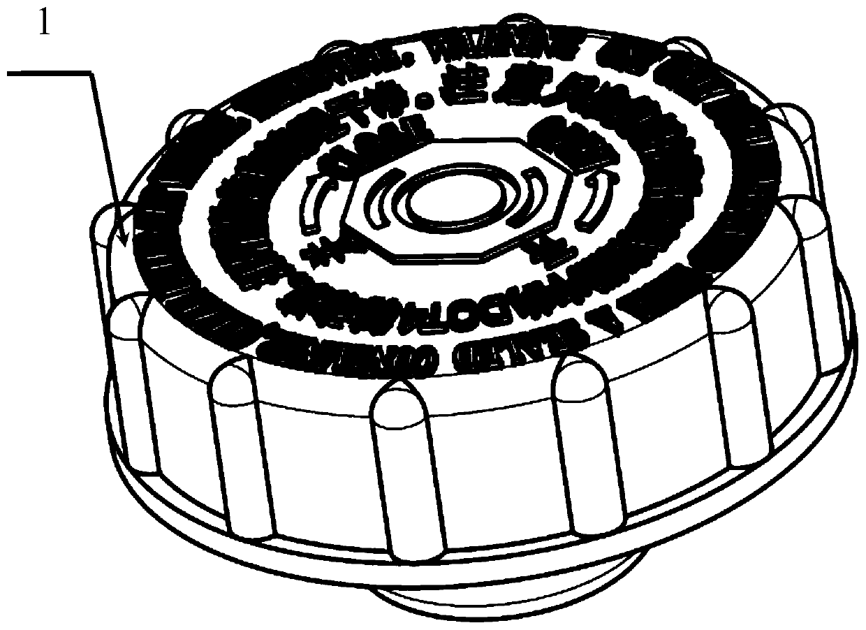
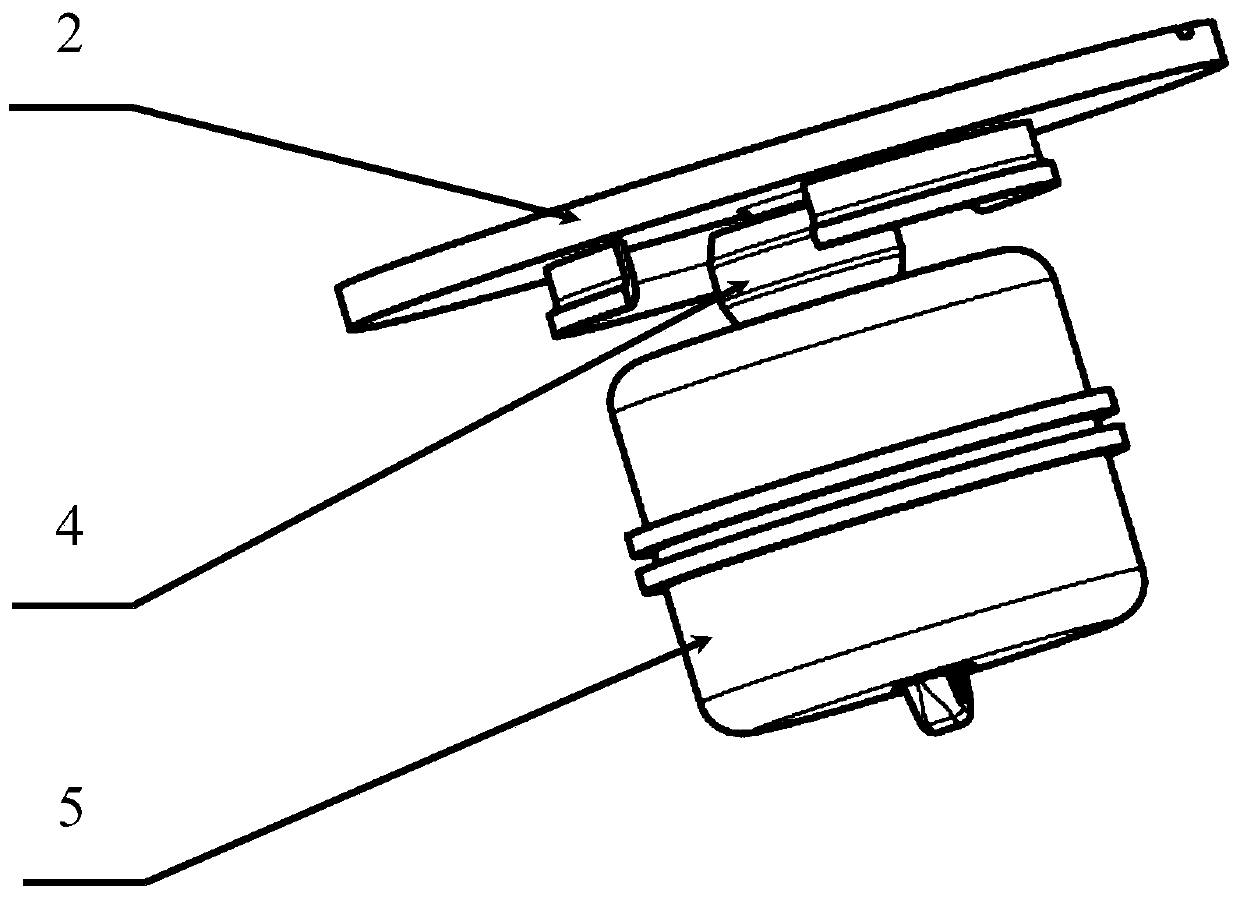
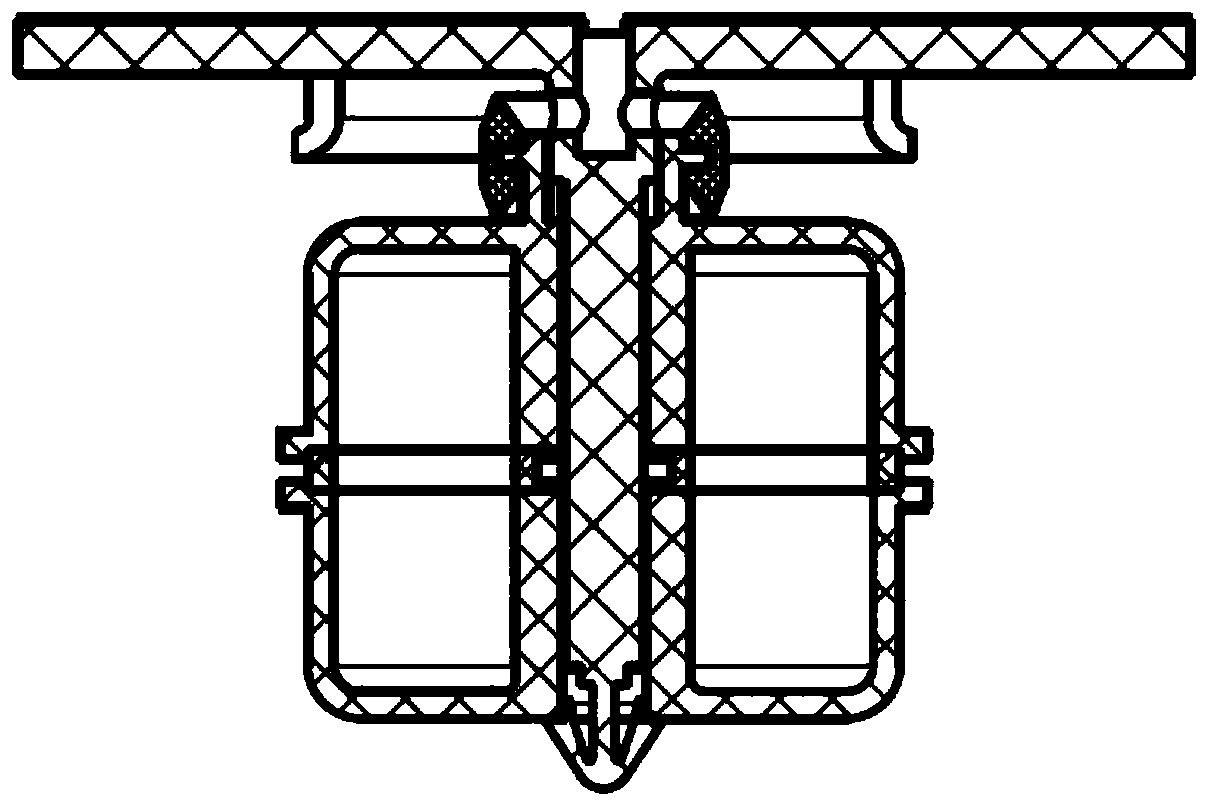

Image

  • Novel liquid storage and filling cover belt oil-blocking ventilation mechanism assembly for automobile
  • Novel liquid storage and filling cover belt oil-blocking ventilation mechanism assembly for automobile
  • Novel liquid storage and filling cover belt oil-blocking ventilation mechanism assembly for automobile

Examples


Embodiment Construction

[0032] The present invention will be further described below in conjunction with drawings and embodiments.

[0033] Such as Figure 1-Figure 2 As shown, the specific implementation of the present invention includes a liquid storage filling cap 1, an oil inlet rubber sealing ring 3, a vent rubber sealing ring 4, a sealing bracket 2, and a floating block 5, and the sealing support 2 and the floating block 5 are all installed in the liquid storage tank. In the cover 1, the floating block 5 is set on the bottom of the sealing bracket 2 and is connected with the rubber sealing ring 4 of the vent hole. The liquid filling cover 1 is installed on the oil inlet 6 of the liquid storage tank.

[0034] Such as image 3 As shown, the inner peripheral surface of the liquid storage cap 1 is provided with an internal thread 11, and the internal thread 11 is connected and screwed to the external thread on the outer peripheral surface of the oil inlet 6 of the liquid storage tank to form a th...


PUM


Abstract

The invention discloses a novel liquid storage and filling cover belt oil-blocking ventilation mechanism assembly for an automobile, which comprises a liquid storage filling cover, an oil inlet rubbersealing ring, a vent rubber sealing ring, a sealing bracket, a floating block, the sealing bracket and the floating block are both arranged in the liquid storage filling cover; the floating block issleeved with the bottom of the sealing bracket and is connected with the vent rubber sealing ring; the end surface of the bottom of the sealing bracket is connected to the end surface of an oil inletof a liquid storage tank through the oil inlet rubber sealing ring; the liquid storage filling cover is arranged at the oil inlet of the liquid storage tank, the sealing bracket is provided with an air communication channel which is communicated with the outside atmosphere and the inner side of the oil inlet of the liquid storage tank, and the upper movement of the floating block under the impactof oil liquid drives the vent rubber sealing ring to seal at the air communication channel. The assembly can effectively avoid the problem that the liquid in the liquid storage tank leaks from the oilinlet of the liquid storage tank when the automobile is bumped and braked in an emergency, and has the advantages of unique design and reliable and stable performance.

Description

technical field [0001] The invention relates to a cover assembly of a liquid storage tank, in particular to a novel liquid storage filling cover assembly with an oil-blocking ventilation mechanism for automobiles. Background technique [0002] In the traditional automobile brake fluid storage cap assembly, the internal ventilation and oil resistance structure is often just a small gap cut in the center of the thin rubber sealing ring, or a swivel channel is designed inside the sealing bracket to achieve the ventilation and oil resistance effect, but These two traditional oil-blocking and ventilating structures can only resist the liquid splash caused by the bumping of the car. It is difficult to resist the rapid impact of the liquid in the liquid storage tank on the liquid storage tank cover when the car is in emergency braking, and there will often be brake fluid Leaking from the liquid storage cap, dripping into the front engine compartment of the car, and even the leaked ...

Claims


Application Information

Patent Timeline
IPC IPC(8): B60T17/06B60T17/00
Inventor 顾江慧李学佳王石雄张殿东何东
Owner ZHEJIANG ASIA PACIFIC MECHANICAL & ELECTRONICS
Learn More