Full-automatic tying machine

A strapping machine, fully automatic technology, applied in the parts, packaging and other directions of strapping machinery, can solve problems such as unstable placement, product damage, product easily placed crooked or tilted, etc., to improve the strapping effect, high degree of automation, The effect of high work efficiency

Inactive Publication Date: 2019-06-28
深圳市思泰宇科技有限公司
View PDF6 Cites 0 Cited by
  • Summary
  • Abstract
  • Description
  • Claims
  • Application Information

AI Technical Summary

Problems solved by technology

[0003] The existing automatic strapping machine is usually sent to the strapping mechanism by the conveyor belt for strapping, but in actual use, the staff usually put the product to be strapped on the conveyor belt, because the placement position is not fixed, the product is easy to be placed crooked or tilted, and the strapping It is easy to cause product damage. Although some correction mechanisms have appeared at present, their structures are complex, especially when the products are placed close to each other and piled up, they cannot be effectively corrected and need to be improved.

Method used


Image

  • Full-automatic tying machine
  • Full-automatic tying machine
  • Full-automatic tying machine

Examples


Embodiment 1

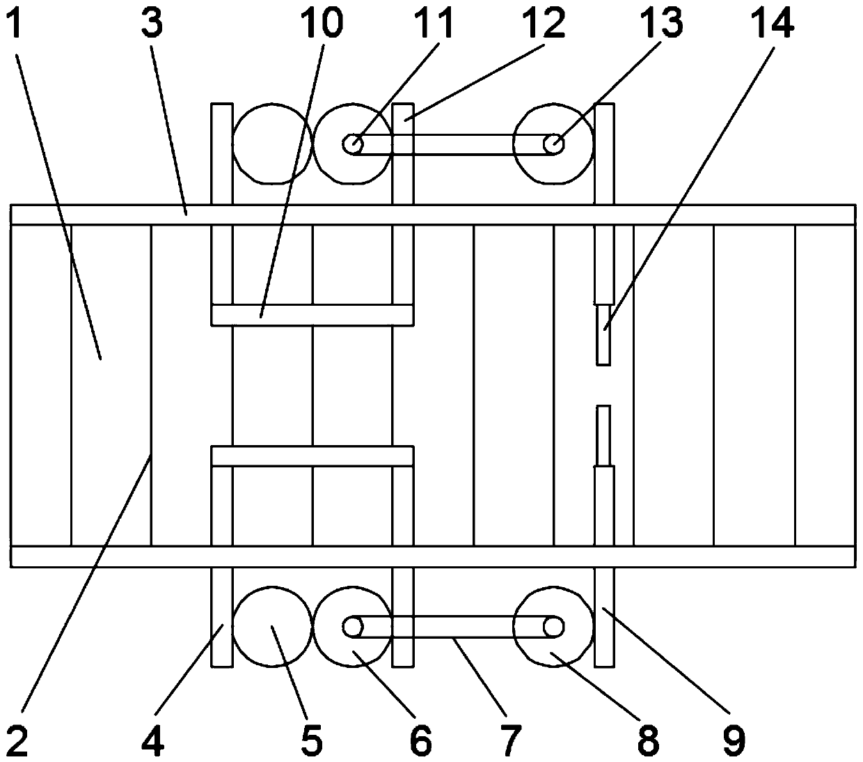
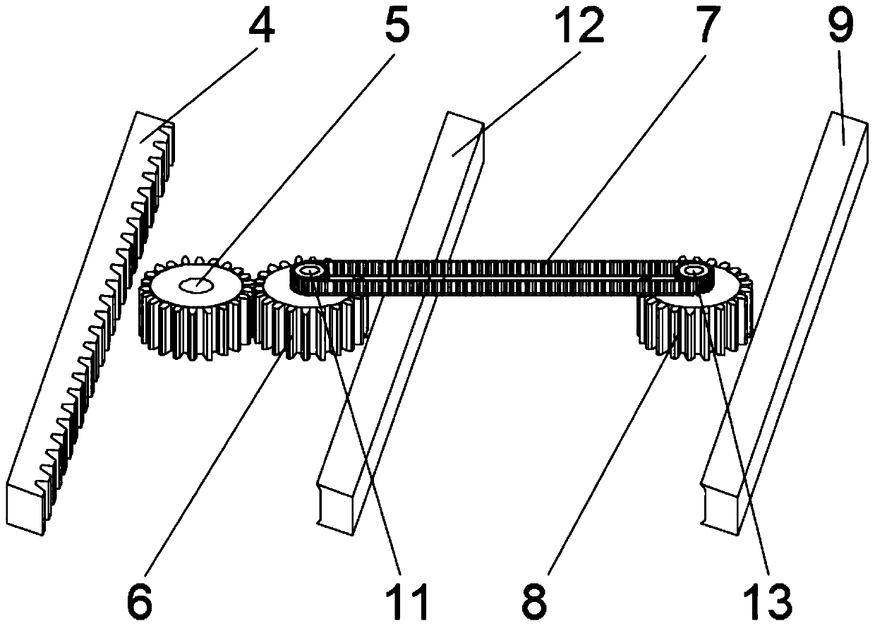
[0024] Such as figure 1 , 2 The full-automatic strapping machine shown includes a strapping mechanism and a transmission mechanism 1. The conveyor mechanism 1 includes a conveyor frame and a conveyor belt 2. The products to be bundled are placed on the conveyor belt 2 and sent to the strapping mechanism through the conveyor belt 2 for strapping. After the strapping is completed, the The bundling of the next product is sent out by the conveyor belt 2, and the existing structure is adopted, and its structure and connection mode are well known to those skilled in the art, and will not be described in detail; A one-by-one correction mechanism is installed, and the products are corrected one by one by installing the one-by-one correction mechanism on the fixed frame 3, which solves the problem of product accumulation and blockage and prevents irregularities when the current strapping machine is used, so that the products to be bundled can be corrected one by one and carried out. B...

Embodiment 2

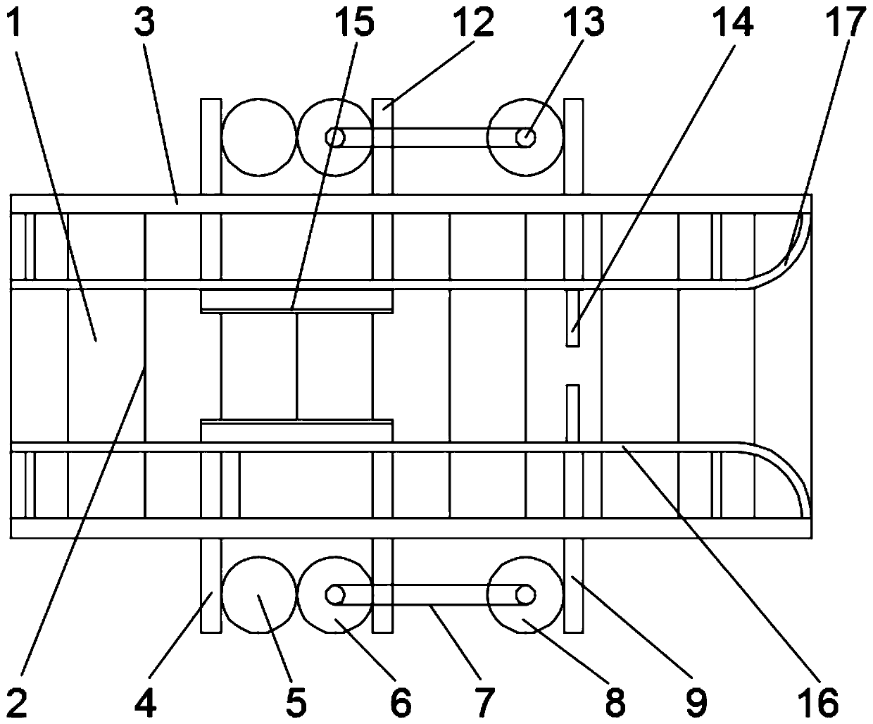
[0027] This embodiment is further optimized on the basis of the embodiment, such as image 3 As shown, the surface of the push plate 10 is fixedly equipped with an anti-skid pad 15, which is soft rubber or soft plastic, and is fixed on the surface of the push plate 10 by gluing or thermoplastic to protect the product to be bundled and prevent the product from being damaged during correction. .

[0028] The inside of the fixed frame 3 is also equipped with a fence 16. The fence 16 is fixedly connected with the fixed frame 3 through a support rod. By setting the fence 16 to constrain the product, it is convenient to form a correction mechanism for correction.

[0029] The fence 16 is fixedly installed with an arc-shaped plate 17 connected thereto, and the arc-shaped plate 17 is arranged on the rear side of the forward direction of the conveyor belt 2, which is convenient for drainage, so that products placed at will can smoothly enter the fence 16, reducing the accuracy of preve...


PUM


Abstract

The invention relates to a full-automatic tying machine and belongs to the technical field of tying equipment. The full-automatic tying machine comprises a tying mechanism and a conveying mechanism. The conveying mechanism comprises a conveying frame and a conveying belt. A fixing frame is fixedly installed on the conveying frame. A one-by-one correcting mechanism is installed on the fixing frame.According to the full-automatic tying machine, products are corrected one by one through the one-by-one correcting mechanism arranged on the conveying mechanism, only one product is discharged and corrected, the problem that the products are piled on the conveying belt, and as a result, the correcting effect is poor is avoided, then the tying effect is improved, the automation degree is high, andthe working efficiency is high.

Description

technical field [0001] The invention relates to the technical field of strapping equipment, in particular to a fully automatic strapping machine. Background technique [0002] The strapping machine, commonly known as the strapping machine, is a machine that uses straps to wrap products or packages, then tightens them and fuses the two ends through thermal effects or connects them with buckles and other materials. The function of the strapping machine is to make the plastic belt stick closely to the surface of the package to be bundled, so as to ensure that the package will not be scattered due to poor binding during transportation and storage, and at the same time, it should be bundled neatly and beautifully. The strapping machine is a machine that bundles packages with strapping straps to complete the strapping operation. The binding device of the strapping machine, which is composed of the frame, the cutter body structure, the camshaft, the electric heating head swing rod...

Claims


Application Information

Patent Timeline
IPC IPC(8): B65B13/18B65B35/56B65B35/24
Inventor 王忠山
Owner 深圳市思泰宇科技有限公司
Why Eureka
Try Eureka