Manufacturing method of injection-molded high-frequency copper clad laminate

A manufacturing method and technology for copper clad laminates, which are used in household components, applications, household appliances, etc., can solve the problems of insufficient dielectric loss, uneven material mixing, easy falling off, etc., so as to reduce dielectric loss, improve bonding effect, The effect of improving stability

Pending Publication Date: 2022-02-08
芜湖精益达模塑股份有限公司
View PDF2 Cites 0 Cited by
  • Summary
  • Abstract
  • Description
  • Claims
  • Application Information

AI Technical Summary

Problems solved by technology

[0005] However, the above-mentioned solutions cannot be injection-molded high-frequency copper-clad laminates, and there are still problems such as uneven material mixing, insufficient dielectric loss, poor bonding effect of copper film, and easy to fall off.

Method used


Image

  • Manufacturing method of injection-molded high-frequency copper clad laminate

Examples


Embodiment 1

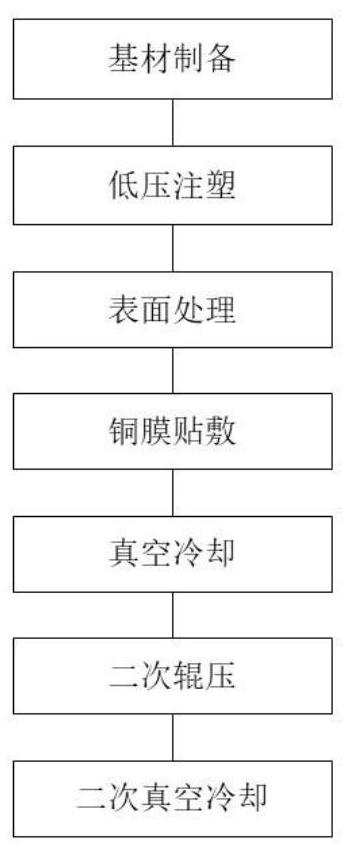
[0044] The manufacturing method of injection molding high frequency copper clad laminate includes:

[0045] Step 1, substrate preparation

[0046] The base materials will be prepared according to the quality: 300 parts of phenolic resin, 200 parts of epoxy resin, 200 parts of polyethylene, 5 parts of magnesium hydroxide, 200 parts of cyclodextrin, 150 parts of nano-alumina powder and 150 parts of silicon dioxide;

[0047] Mix the prepared base materials, put them into a ball mill for ball milling after mixing, and ensure that the ball milling temperature does not exceed 50°C during the ball milling process;

[0048] Ball mill until the particle size of the base material is less than 0.05mm, put the base material into a heating container for heating, heat to 300°C to make the base material flow as a whole, then cool down and extrude to make base material particles;

[0049] Step 2. Low pressure injection molding

[0050] Add epoxy resin curing agent to the substrate particles...

Embodiment 2

[0073] Step 1, substrate preparation

[0074] The base materials will be prepared according to the quality: 200 parts of phenolic resin, 100 parts of epoxy resin, 100 parts of polyethylene, 1 part of magnesium hydroxide, 100 parts of cyclodextrin, 100 parts of nano-alumina powder and 100 parts of silicon dioxide;

[0075] Mix the prepared base materials, put them into a ball mill for ball milling after mixing, and ensure that the ball milling temperature does not exceed 50°C during the ball milling process;

[0076] Ball mill until the particle size of the base material is less than 0.05mm, put the base material into a heating container for heating, heat to 300°C to make the base material flow as a whole, then cool down and extrude to make base material particles;

[0077] Step 2. Low pressure injection molding

[0078] Add epoxy resin curing agent to the substrate particles obtained in step 1, mix and heat, heat to 250°C and inject into a low-pressure injection mold, and kee...

Embodiment 3

[0086] Step 1 also includes an ultrasonic oscillation mixing step, specifically:

[0087] Ultrasonic mixing is performed on the ball-milled base material before heating, that is, the ball-milled base material is placed on an ultrasonic oscillator for ultrasonic mixing, the oscillation time is 10-15min, and the oscillation frequency is 150kHz-300kHz.


PUM

PropertyMeasurementUnit
Thicknessaaaaaaaaaa
Thicknessaaaaaaaaaa

Abstract

The invention relates to a manufacturing method of an injection-molded high-frequency copper clad laminate. According to the invention, materials of an injection molding base material are reconfigured, and cyclodextrin, silicon dioxide, magnesium hydroxide, nano aluminum oxide and polyethylene are added, wherein addition of the cyclodextrin and the polyethylene is beneficial to reducing dielectric loss of a copper clad laminate, and addition of the magnesium hydroxide, the nano aluminum oxide and the silicon dioxide can improve surface light absorption and treatment effects during laser processing; double laser is used for surface treatment before a copper film is pasted, so that the combination effect of the copper film and a substrate is improved, and stability of subsequent rolling is improved; and a centrifugal machine is used for centrifuging before injection molding, so that impurities at the bottom can be fully removed while bubbles are removed.

Description

technical field [0001] The invention relates to the technical field of copper-clad laminate preparation, in particular to a method for manufacturing an injection-molded high-frequency copper-clad laminate. Background technique [0002] Copper-clad laminate is the basic material of the electronics industry and an indispensable main component for most electronic products to achieve circuit interconnection. It can be divided into paper substrates, composite substrates, FR-4 copper-clad laminates, halogen-free boards, high-frequency copper-clad laminates, packaging substrates, etc. The evolution of copper clad laminate technology has gone through the gradual upgrading process of "common board → lead-free halogen free board → high frequency and high speed / vehicle use / IC packaging / high thermal conductivity board". With the development of communication technology, the use of high frequency copper clad laminate is becoming more and more more. [0003] The application number CN2017...

Claims


Application Information

Patent Timeline
IPC IPC(8): B29C69/00B29C45/00B29C59/16B29C65/02B29C65/52B29C35/16B29B13/10C08L61/06C08L63/00C08L23/06C08L5/16C08K3/22C08K3/36B29L31/34
CPCB29C69/00B29C45/00B29C59/16B29C66/45B29C65/02B29C65/52B29C35/16B29B13/10C08L61/06C08K2201/011C08K2003/2227C08K2003/2224B29L2031/34C08L63/00C08L23/06C08L5/16C08K3/22C08K3/36
Inventor 翟超
Owner 芜湖精益达模塑股份有限公司
Why Eureka
Try Eureka