Unlock instant, AI-driven research and patent intelligence for your innovation.

Mechanisms, components and electronic locking systems

A technology for locking systems and components, applied in the direction of electric components, electromechanical devices, locks operated by non-mechanical transmission, etc., can solve problems such as complexity, low energy efficiency, and large structural design

Active Publication Date: 2021-06-22
ASSA ABLOY AB
View PDF6 Cites 0 Cited by
  • Summary
  • Abstract
  • Description
  • Claims
  • Application Information

AI Technical Summary

Problems solved by technology

Disadvantages of the device in US 2014 / 0225375 A1 include low energy efficiency and bulky structural design, which complicates installation of the device in a door

Method used


Image

  • Mechanisms, components and electronic locking systems
  • Mechanisms, components and electronic locking systems
  • Mechanisms, components and electronic locking systems

Examples


Embodiment Construction

[0111] The present invention will now be described more fully hereinafter with reference to the accompanying drawings, in which specific embodiments of the invention are shown. However, this invention may be embodied in many different forms and should not be construed as limited to the embodiments set forth herein; rather, these embodiments are provided by way of example so that this disclosure will be thorough and complete, and will The scope of the present invention is fully conveyed to those skilled in the art. Like reference numerals refer to like elements throughout this specification.

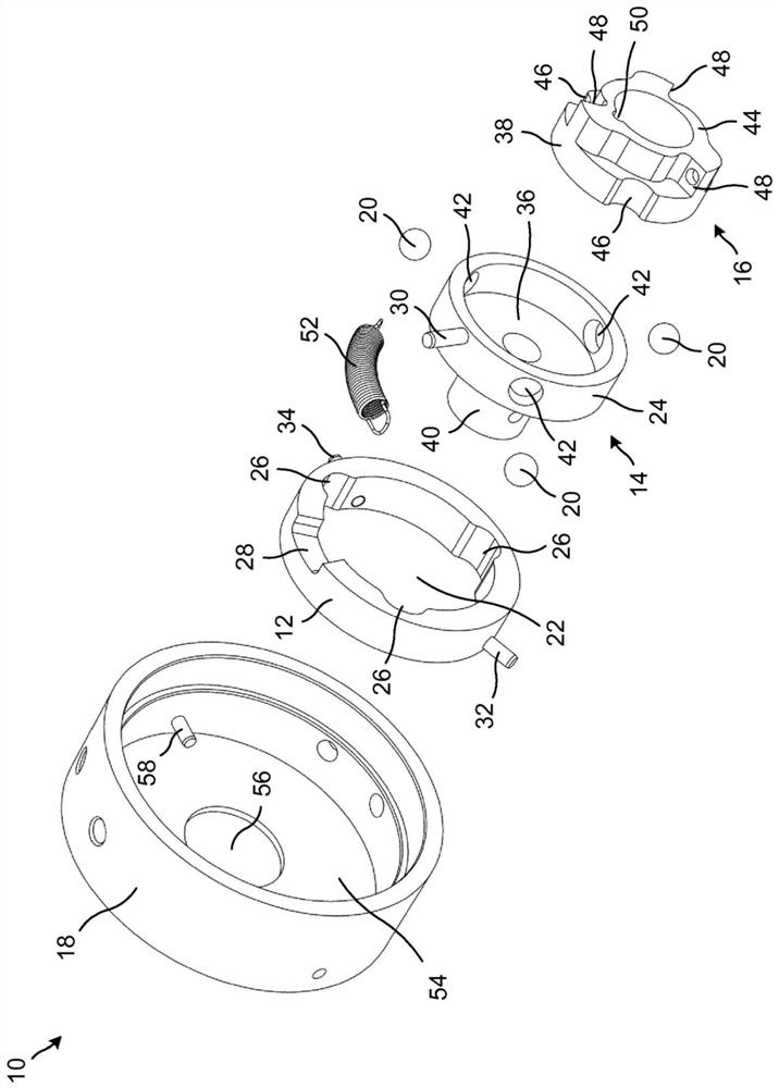
[0112] figure 1 An exploded perspective view of the release mechanism 10 is schematically illustrated. The release mechanism 10 includes a locking ring 12 , an input member 14 and an output member 16 . The release mechanism 10 of this example also includes a securing structure 18 . The fastening structure 18 forms a housing or housing for the components of the release mechanism 10 . ...


PUM


Abstract

A release mechanism (10) for an electronic locking system (156), wherein the release mechanism (10) is configured such that when the locking member (20) is located in the input member recess (42) and in the output member recess (46) In neutral, the input member (14) and output member (16) are locked against relative rotation and the input member (14) and output member (16) can rotate together within the locking ring opening (22) and the release mechanism (10) Configured so that when the locking member (20) is located in the output member recess (46) and in the locking ring recess (26), the output member (16) is released to rotate relative to the input member (14). A flywheel mechanism (66) and assembly (98) for an electronic locking system (156) is also provided.

Description

technical field [0001] The present disclosure generally relates to mechanisms and components for electronic locking systems. In particular, release mechanisms, flywheel mechanisms and assemblies for electronic locking systems are provided. Background technique [0002] Various types of electronic locking systems are known. Instead of utilizing a purely mechanical lock, some locking systems include electronic actuation of a locking member (eg, a deadbolt) to, for example, open a door for access to an area behind the door. [0003] Furthermore, instead of using a traditional key to open the door, various types of electronic communication methods are known for authorizing personnel to enter the area behind the door. For example, a Radio Frequency Identification (RFID) system may be used, in which case a reader of the RFID system is installed in the door and a tag is carried by, or attached to, the object to be identified. [0004] In order to power electronic locking systems...

Claims


Application Information

Patent Timeline
Patent Type & Authority Patents(China)
IPC IPC(8): E05B3/06E05B13/00E05B47/00
CPCE05B3/065E05B13/005E05B2047/0062E05B47/0001H02K7/02H02K7/1853G07C2009/00634G07C2009/00388G07C9/00174
Inventor 安德斯·科斯特丹尼尔·斯卡尔普罗宾·麦高根亨利克·斯文松伯恩特·阿尔贝加德
Owner ASSA ABLOY AB
Features
  • R&D
  • Intellectual Property
  • Life Sciences
  • Materials
  • Tech Scout
  • Unparalleled Data Quality
  • Higher Quality Content
  • 60% Fewer Hallucinations
Learn More