Ejection device

A technology of ejecting device and guide block, which is applied in the field of die-casting molds, can solve the problems that a part of the needle is still left, and the ejector plate cannot be ejected to a predetermined height, etc., so as to achieve the effect of complete ejection.

Inactive Publication Date: 2019-07-02
钱碧春
View PDF0 Cites 1 Cited by
  • Summary
  • Abstract
  • Description
  • Claims
  • Application Information

AI Technical Summary

Problems solved by technology

[0003] Die-casting has high production efficiency and can die-cast injection molded parts with complex shapes, precise dimensions, clear outlines, high surface quality, strength, and hardness. In order to facilitate the removal of injection molded parts and not damage the shape and surface integrity of injection molded parts when taking out injection molded parts , the mold is generally equipped with an ejection mechanism, which can safely eject the die-cast casting out of the mold, and effectively protect the injection molded part from damage as a whole. The needle assembly includes a thimble and a cylinder. The interior of the cylinder is hollow. The cylinder is installed on the ejector plate and fixedly connected with the ejector plate. The lower end of the injection molded part has a downward protruding ejector cylinder. Installed on the bottom plate and pass through the inside of the cylinder and the top of the thimble is inserted into the injection molded part to withstand it. The thimble plate is installed on the upper surface of the bottom plate. A spring is installed between the thimble plate and the bottom plate. Under the action, the top of the cylinder moves upwards, and the top of the cylinder touches the lower surface of the ejector cylinder and moves upward with the ejector plate to push the injection molded part upwards against the cylinder so that the ejector cylinder is separated from the ejector pin, and finally the injection molded part is ejected. Although this ejection structure The injection molded parts can be ejected, but there are still the following problems: because the upward movement of the ejector plate is realized by the elastic force of the spring, and the elastic force of the spring will continue to weaken and fade during the long-term telescopic movement, and in this case, Since the self-gravity of the ejector plate remains unchanged, the spring cannot push the ejector plate to the predetermined height when the elastic force is weakened, and the cylinder cannot completely eject the injection molded part out of the range of the ejector pin, resulting in a part of the ejector pin remaining on the ejector cylinder of the injection molded part If the injection molded part is not fully ejected, if the staff moves the injection molded part at this time, the injection molded part will be damaged, resulting in serious damage to the injection molded part

Method used


Image

  • Ejection device
  • Ejection device
  • Ejection device

Examples


Embodiment Construction

[0021] The following are specific embodiments of the present invention and in conjunction with the accompanying drawings, the technical solutions of the present invention are further described, but the present invention is not limited to these embodiments.

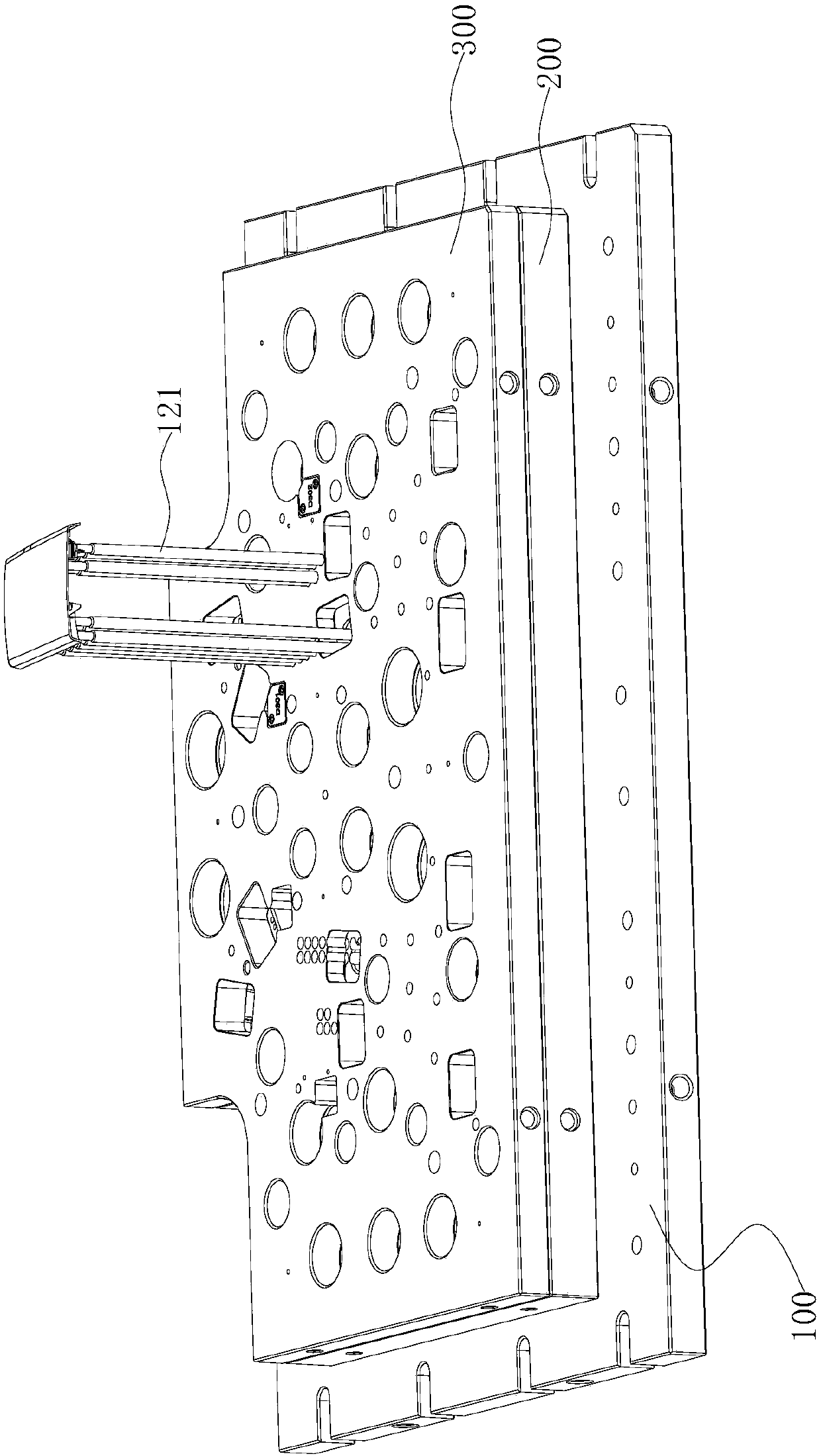
[0022] Such as figure 1 figure 2 As shown, an ejector device of the present invention comprises a fixed mold base plate 100, on which a lower needle plate 200 and an upper needle plate 300 are sequentially installed from bottom to top, and the bottom surface of the lower needle plate 200 is pressed against the fixed mold base plate. On the upper end surface of the base plate 100, the bottom end surface of the upper needle plate 300 is pressed against the upper end surface of the lower needle plate 200, and a mold foot is fixedly installed on both sides of the fixed die base plate 100, and a lower mold is installed on the upper end surface of the mold foot. The two ends rest on the two mold feet respectively. The upper en...


PUM


Abstract

The invention provides an ejection device, and belongs to the technical field of die-casting dies. The ejection device solves the technical problems that a spring in an existing ejection device is prone to lose efficiency, an injection molded part cannot be completely ejected out, then the injection molded part is easily damaged by pulling are solved; the ejection device comprises a fixed mold bottom plate, wherein an ejection needle plate and a lower needle plate are arranged on the fixed mold bottom plate, an ejector sleeve is arranged on the ejection needle plate and penetrates through thelower needle plate, a centre is fixedly arranged on the fixed mold bottom plate, the centre penetrates through the ejector sleeve, the upper end surface of the centre exceeds the upper end surface ofthe ejector sleeve, and the lifting mechanism is fixedly arranged on the lower needle plate; and the lifting mechanism is movably connected with the ejection needle plate and enables the ejection needle plate to rise along with the lower needle plate, when the ejection needle plate pushes the ejector sleeve to rise and the upper end of the ejector sleeve is flush with the upper end of the centre,the lifting mechanism is separated from the ejection needle plate. The ejection device has the beneficial effects that the device is not affected by the failure of the spring, so that the injection molded part can be safely and completely ejected out, and it is guaranteed that the injection molded part is not damaged.

Description

technical field [0001] The invention belongs to the technical field of die-casting molds, and relates to an ejector device. Background technique [0002] Die-casting process is a high-efficiency and less metal-cutting forming process. Die-casting process is used to produce various metal parts in modern industry. It has unique technical characteristics and significant economic benefits. The principle of die-casting process is to use high pressure to The molten metal is pressed into the cavity of a precision metal mold with a specific shape at high speed. The molten metal is cooled and solidified under the action of pressure. After the molten metal solidifies, the die-casting mold is opened, and the casting is taken out to complete a die-casting cycle. [0003] Die-casting has high production efficiency and can die-cast injection molded parts with complex shapes, precise dimensions, clear outlines, high surface quality, strength, and hardness. In order to facilitate the remova...

Claims


Application Information

Patent Timeline
Patent Type & Authority Applications(China)
IPC IPC(8): B22D17/22
CPCB22D17/2236
Inventor 钱碧春
Owner 钱碧春
Why Eureka
Try Eureka