

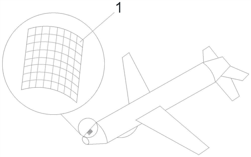
High-gain conformal antenna suitable for head of high-speed aircraft
A high-speed aircraft, high-gain technology, applied to antennas suitable for movable objects, individually energized antenna arrays, antennas, etc., can solve problems such as increasing the radar cross section of aircraft, deadly stealth aircraft, and affecting aircraft aerodynamic characteristics. , to achieve the effect of wide beam coverage, avoiding rapid drop, and high gain
- Summary
- Abstract
- Description
- Claims
- Application Information
AI Technical Summary
Problems solved by technology
Method used
Image

Examples
Embodiment Construction
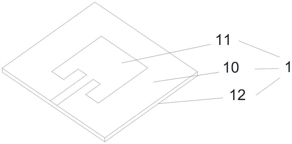
[0022] Embodiments of the present invention will be described in detail below, and examples of the embodiments are illustrated in the drawings, in which the same or similar reference numerals represent the same or similar elements or elements having the same or similar functions. The following is exemplary, and is intended to be used to illustrate the invention without understanding the limitation of the invention.
[0023] In the description of the present invention, it is to be understood that the terms "length", "width", "upper", "lower", "front", "post", "left", "right", "vertical", The orientation of the "horizontal", "top", "bottom", "inside", "outside", etc., is based on the orientation or positional relationship shown in the drawings, is only for ease of describing the invention and simplified description, not Indicating or implying that the device or element must have a specific orientation, constructed and operated in a particular orientation, and thus is not to be const...
PUM
 Abstract
Description
Claims
Application Information